A practical approach to Kalman filter and how to implement it
I have for a long time been interrested in Kalman filers and how they work, I also used a Kalman filter for my Balancing robot, but I never explained how it actually was implemented. Actually I had never taken the time to sit down with a pen and a piece of paper and try to do the math by myself, so I actually did not know how it was implemented.
It turned out to be a good thing, as I actually discovered a mistake in the original code, but I will get back to that later.
I actually wrote about the Kalman filter as my master assignment in high school back in December 2011. But I only used the Kalman filter to calculate the true voltage of a DC signal modulated by known Gaussian white noise. My assignment can be found in the following zip file: http://www.tkjelectronics.dk/uploads/Kalman_SRP.zip. It is in danish, but you can properly use google translate to translate some of it. If you got any specific questions regarding the assignment, then ask in the comments below.
Okay, but back to the subject. As I sad I had never taken the time to sit down and do the math regarding the Kalman filter based on an accelerometer and a gyroscope. It was not as hard as I expected, but I must confess that I still have not studied the deeper theory behind, on why it actually works. But for me, and most people out there, I am more interrested in implementing the filter, than in the deeper theory behind and why the equations works.
Before we begin you must have some basic knowledge about matrices like multiplication of matrices and transposing of matrices. If not then please take a look at the following websites:
- http://en.wikipedia.org/wiki/Matrix_multiplication#Matrix_product_.28two_matrices.29
- http://www.mathwarehouse.com/algebra/matrix/multiply-matrix.php
- http://en.wikipedia.org/wiki/Transpose
- http://en.wikipedia.org/wiki/Covariance_matrix
For those of you who do not know what a Kalman filter is, it is an algorithm which uses a series of measurements observed over time, in this context an accelerometer and a gyroscope. These measurements will contain noise that will contribute to the error of the measurement. The Kalman filter will then try to estimate the state of the system, based on the current and previous states, that tend to be more precise that than the measurements alone.
In this context the problem is that the accelerometer is in general very noise when it is used to measure the gravitational acceleration since the robot is moving back and forth. The problem with the gyro is that it drifts over time – just like a spinning wheel-gyro will start to fall down when it is losing speed.
In short you can say that you can only trust the gyroscope on a short term while you can only trust the accelerometer on a long term.
There is actually a very easy way to deal with this by using a complimentary filter, which basicly just consist of a digital low-pass filter on the accelerometer and digital high-pass filter on the gyroscope readings. But it is not as accurate as the Kalman filter, but other people have succesfully build balancing robots using a fine-tuned complimentary filter.
More information about gyroscopes, accelerometer and complimentary filters can be found in this pdf. A comparison between a complimentary filter and a Kalman filter can be found in the following blog post.
The Kalman filter operates by producing a statistically optimal estimate of the system state based upon the measurement(s). To do this it will need to know the noise of the input to the filter called the measurement noise, but also the noise of the system itself called the process noise. To do this the noise has to be Gaussian distributed and have a mean of zero, luckily for us most random noise have this characteristic.
For more information about the theory behind the filter take a look at the following pages:
- http://en.wikipedia.org/wiki/Kalman_filter
- http://www.cs.unc.edu/~welch/media/pdf/kalman_intro.pdf
- http://academic.csuohio.edu/simond/courses/eec644/kalman.pdf
The system state
The next of this article might seem very confusing for some, but I promise you if you grab a pen and a piece of paper and try to follow along it is not that hard if you are reasonable at math.

If you, like me, do not have a calculator or computer program that can work with matrices, then I recommend the free online calculator Wolfram Alpha. I used it for all the calculations in this article.
I will use the same notation as the wikipedia article, but I will like to note that when the matrixes are constants and does not depend on the current time you do not have to write the k after them. So for instance 

Also I would like to write a small explanation of the other aspects of the notations.
First I will make a note about whats called the previous state:

Which is the previous estimated state based on the previous state and the estimates of the states before it.
The next is the a priori state:

A priori means the estimate of the state matrix at the current time k based on the previous state of the system and the estimates of the states before it.
The last one is called a posteriori state:

Is the estimated of the state at time k given observations up to and including at time k.
The problem is that the system state itself is hidden and can only be observed through observation 
This means that the state will be based upon the state at time k and all the previous states. That also means that you can not trust the estimate of the state before the Kalman filter has stabilized – take a look at the graph at the front page of my assignment.
The hat over the 

So the notation for the state at time k is:

The state of the system at time k if given by:

Where 

As you can see the output of the filter will be the angle 

The next is the 
In this case

I know that the 
The next is the control input 


The next thing is the 

This makes perfectly sense as you will get the angle 


")

The final matrix is defined as so:

As you can see the 

This makes sense as the process noise will be larger as longer time it is since the last update of the state. For instance the gyro could have drifted.
You will have to know these constants for the Kalman filter to work.
Note if you set a larger value, the more noise in the estimation of the state. So for instance if the estimated angle starts to drift you have to increase the value of
The measurement
Now we will take a look at the observation or measurement


As you can see the measurement 


The noise of the measurement have to be Gaussian distributed as well with a zero mean and 
")
But as
Now we can define
")
More information about covariance can be found on Wikipedia and in my assignment.
We will assume that the measurement noise is the same and does not depend on the time k:
 = var(v)")
Note that if you set the measurement noise variance ")
So to round up you have to find the the process noise variances
The Kalman filter equations
Okay now to the equations we will use to estimate the true state of the system at time k 
The equations can be written more compact, but I prefer to have them stretched out, so it is easier to implement and understand the different steps.
Predict
In the first two equations we will try to predict the current state and the error covariance matrix at time k. First the filter will try to estimate the current state based on all the previous states and the gyro measurement:

That is also why it is called a control input, since we use it as an extra input to estimate the state at the current time k called the a priori state
 as described in the beginning of the article.
The next thing is that we will try to estimate the a priori error covariance matrix 


This matrix is used to estimate how much we trust the current values of the estimated state. The smaller the more we trust the current estimated state. The principle of the equation above is actually pretty easy to understand, as it is pretty obvious that the error covariance will increase since we last updated the estimate of the state, therefore we multiplied the error covariance matrix by the state transition model 
The error covariance matrix 

Update
The fist thing we will do is to compute the difference between the measurement 

The observation model

The next thing we will do is calculate whats called the innovation covariance:

What it does is that it tries to predict how much we should trust the measurement based on the a priori error covariance matrix
and the measurement covariance matrix . The observation model is used to map the a priori error covariance matrix into observed space.
The bigger the value of the measurement noise the larger the value of 
In this case

The next step is to calculate the Kalman gain. The Kalman gain is used to to indicate how much we trust the innovation and is defined as:

You can see that if we do not trust the innovation that much the innovation covariance
If you take a deeper look you can see that the transpose of the observation model
This make sense as we will use the observation model
Note that if you do not know the state at startup you can set the error covariance matrix like so:

Where
 represent a large number.
For my balancing robot I know the starting angle and I find the bias of the gyro at startup by calibrating, so I assume that the state will be known at startup, so I initialize the error covariance matrix like so:

Take a look at my calibration routine for more information.
In this case the Kalman gain is a 2×1 matrix:

Now we can update the a posteriori estimate of the current state:

This is done by adding the a priori state
with the Kalman gain multiplied by the innovation  .
.Remember that the innovation
is the difference between the measurement and the estimated priori state , so the innovation can both be positive and negative.
A little simplified the equation can be understood as we simply correct the estimate of the a priori state
The last thing we will do is update the a posteriori error covariance matrix:
 \boldsymbol{P}_{k | k-1}")
Where 

What the filter is doing is that it is basically self-correcting the error covariance matrix based on how much we corrected the estimate. This make sense as we corrected the state based the a priori error covariance matrix 
Implementing the filter
In this section I will use the equation from above to implement the filter into a simple c++ code that can be used for balancing robots, quadcopters and other applications where you need to compute the angle, bias or rate.
In case you want the code next to you, it can be found at github: https://github.com/TKJElectronics/KalmanFilter.
I will simply write the equations at the top of each step and then simplify them after that I will write how it is can be done i C and finally I will link to calculations done in Wolfram Alpha in the bottom of each step, as I used them to do the calculation.
Step 1:


 \\ \dot{\theta}_b \end{bmatrix}")
As you can see the a priori estimate of the angle is 

Since we can not directly measure the bias the estimate of the a priori bias is just equal to the previous one.
This can be written in C like so:
angle += dt * rate;
Note that I calculate the unbiased rate, so it can be be used by the user as well.
Wolfram Alpha links:
Step 2:


 & P_{01} -\Delta t P_{11} \\ P_{10} -\Delta t P_{11} & P_{11} \end{bmatrix}_{k-1 | k-1} + \begin{bmatrix} Q_\theta & 0 \\ 0 & Q_{\dot{\theta}_b} \end{bmatrix}\Delta t")
 + Q_\theta \Delta t & P_{01} -\Delta t P_{11} \\ P_{10} -\Delta t P_{11} & P_{11} + Q_{\dot{\theta}_b} \Delta t \end{bmatrix}")
 & P_{01} -\Delta t P_{11} \\ P_{10} -\Delta t P_{11} & P_{11} + Q_{\dot{\theta}_b} \Delta t \end{bmatrix}")
The equations above can be written in C like so:
P[0][1] -= dt * P[1][1];
P[1][0] -= dt * P[1][1];
P[1][1] += Q_gyroBias * dt;
Note that this is the part of the code that there was an error in in the original code that I used.
Wolfram Alpha links:
Step 3:


The innovation can be calculated in C like so:
Wolfram Alpha links:
Step 4:


")
Again the C code is pretty simple:
Wolfram Alpha links:
Step 5:


Note that in other cases
The C implementation looks like this:
K[1] = P[1][0] / S;
Wolfram Alpha links:
Step 6:


Yet again the equation end up pretty short, and can be written as so in C:
bias += K[1] * y;
Step 7:
 \begin{bmatrix} P_{00} & P_{01} \\ P_{10} & P_{11} \end{bmatrix}_{k | k-1}")
 \begin{bmatrix} P_{00} & P_{01} \\ P_{10} & P_{11} \end{bmatrix}_{k | k-1}")

Remember that we decrease the error covariance matrix again, since the error of the estimate of the state has been decreased.
The C code looks like this:
float P01_temp = P[0][1];
P[0][0] -= K[0] * P00_temp;
P[0][1] -= K[0] * P01_temp;
P[1][0] -= K[1] * P00_temp;
P[1][1] -= K[1] * P01_temp;
Wolfram Alpha links:
Note that I have found that the following variances works perfectly for most IMUs:
float Q_gyroBias = 0.003;
float R_measure = 0.03;
Remember that it’s very important to set the target angle at startup if you need to use the output at startup. For more information, see the calibration routine for my balancing robot.
In case you missed it here is the library I wrote a library that can be used by any microcontroller that supports floating math. The source code can be found at github: https://github.com/TKJElectronics/KalmanFilter.
If you prefer a video explanation about the Kalman filter, I recommend the following video series: http://www.youtube.com/watch?v=FkCT_LV9Syk.
Note that you can not use the library if you need to represent something in a full 3D orientations, as euler angles suffer from what is called Gimbal lock you will need to use Quaternions to do that, but that is a whole nother story. For now take a look at the following page.
This is all for know, I hope that you will find i helpfull, if you do or have any questions fell free to post a comment below – it supports LaTeX syntax as well, if you need to write equations.
If you spot any errors please let me know as well.
Thanks for the great article and for the reference to filter.pdf (my document from ages ago…). This is definitely one of the better explanations I’ve seen about making a Kalman filter for angle estimation based on accelerometer/gyro data.
What do you think about the idea of pre-computing the P, S, and K values? They should converge independent of the states and measurements. In the steady-state, it seems like you would be back to a complementary filter with K[0]’s steady-state value and a simple bias estimator with K[1]’s steady-state. Of course, having the computation done in real-time opens up more possibilities (covariance reset, EKF, etc.).
@Shane
Thank you very much. I must say that your pdf and the project details about your balancing robot were a big inspiration too, when I started to look into building a balancing robot.
I see you point. They should end up being constants after some time, as they don’t depend on any incoming data from either gyroscope or accelerometer.
It might be interesting to run the numbers in Matlab and see what P, S, and K end up with. That might be material for a future blog post.
I look forward to it! I’ve been trying to compare the two filters for a long time and this has helped a lot. I just never had a simple enough presentation of the Kalman filter approach to try.
What is the delta-T in your implementation?
@Shane
Okay. I will try to hopefully start working with Matlab in the coming weeks and then I will let you know what conclusion I come up with.
Delta t is the time since the calculation was last performed. See these lines at the example code: https://github.com/TKJElectronics/KalmanFilter/blob/master/examples/KalmanExample/KalmanExample.ino#L45-46.
Great explanation! Many people complain about Kalman Filters, but this surely will help them.
About @Shane’s comment, many industry applications use constant values for the Kalman gain (K), as it converges if the process is stationary. I tried it myself and works very nicely, specially if the processor is not very powerful.
Also, being a Control Engineer, I’d like to add a minor detail: the gimbal lock occurs because of a mechanical characteristic of the system, independently of the mathematical representation. It reflects as a loss of degree of freedom in the Euler angles representations and a singularity in the Jacobian. But the same problem happens with quaternions. Although quaternions don’t suffer from the singularity, and therefore are able to keep tracking the angles, the mechanical gimbal lock still occurs. Think about a robotic arm and you’ll see that sometimes the one of the wrists has to move very (almost infinitely) fast. That occurs because of the singularity in the Euler angles used to build the robot (which can be reflected using Euler angles in the formulation), but will happen even if we use quaternions for tracking (which will be able to track correctly, but the speed will be infinite). Unfortunately, we can’t build robot arms based on quaternions. The problem is in the inverse dynamics.
Finally, from the point of view of filtering, the gimbal lock can only be observed through Euler angles, but from the point of view of control, it can happen because of the mechanics of the robot.
This is the greatest article on this topic I’ve ever seen!
But could you please make a .pdf version too? Or, did I missed the link?
@YS
I have now generated a pdf version of the article. It can be found in the bottom of the article.
@Conrado
Thank you for your clarification! The true is that I have not looked into the theory of quaternions as I have never needed to use them, so it’s nice to get some feedback from people like you!
Thank thee very much!!! I spend two days to read the pager….still a little hard for me, but closer to kalman filter!
Thank you!
Awesome article, really enjoyed it.
Could you please explain about the ‘physical model’ behind the equations? How did you get the matrices F and B.
Thank you!
Very nice article, Lauszus. Truly amazing! Best one I’ve seen so far. Congrats!
You said that you found an error in your original code, can you specify what and where was it?
Thank you very much for this!
@bimmer

Okay. I will try with a example.
Remember that the state is given by:
We will just assume that after some samples the state is equal to:

Which means that the angle is currently 180° and the amount the gyroscope has drifted is equal to 10°/s.
Okay now assume that the output of the gyroscope is measured as 15°/s:

It’s easy to understand that it’s not 15°/s since the bias is 10°/s, so the real rate is 5°/s – this what is we are trying to achieve.
Now we will define the and
and  matrices as we did in the blog post:

Let’s put it into the equation:

So now let’s multiply those matrices:

Now we will add them together:

The end up result will be:

Also check out step 1 for more help.
@Claudio Donaté
See step 2.
I mention it just after the C code.
Lauszus,
I hope your high school teacher gave you an A++! Extremely impressive!!! You’ll go far, I’m sure we’ll be reading about you one day soon.
@Grant Pitzer
Thank you very much. I actually got the highest grade for the assignment (we use a different grading system in Denmark) 🙂
Lauszus,
I just received an email about this TRAX AHRS System. They advertise their use of the Kalman Filter.
http://youtu.be/LEYPILpe0Dk
Keep up the good work!
Ok, I think I am missing something, but how do you obtain z (newAngle) in step 3?
Do you have to integrate the unfiltered signal or do you need to have a some other source?
Thanks.
@Vic
It’s just the angle calculated using the accelerometers. See this example sketch on how to use it: https://github.com/TKJElectronics/Example-Sketch-for-IMU-including-Kalman-filter/blob/master/IMU6DOF/MPU6050/MPU6050.ino#L70
@Lauszus
Thanks for the quick answer.
But I am not sure how this would work in a helicopter for example. Wouldn’t this only work if the accelerometer was standing still (or moving with a constant speed)?
accYangle = (atan2(accX,accZ)+PI)*RAD_TO_DEG;
accXangle = (atan2(accY,accZ)+PI)*RAD_TO_DEG;
If it was standing still it would register -vec{g} but if it was on-board a vehicle, like a helicopter acelerating, it would register -vec{g} + vec{a}.
Finally if I was design a kalman filter for accelerometer should I also use an external source like a gps or ultrasonic range sensor for z? How about if I don’t have any other sensor, just the IMU?
Thanks again!
@Vic
No it should work in a helicopter as long as you don’t start to do loops and so on.
That’s the hole point of this Kalman filter – it combines the angle obtained from the accelerometer and the rate obtained from the gyroscope to calculate the pitch and roll.
Remember that if you wan’t to use other inputs to the filter you’ll have to redefine the matrices.
When you write IMU do you mean only the accelerometer or also the gyroscope?
I mean the accelerometer + gyroscope?
@Lauszus
@Vic
The hole point of this post was to create the code to use with an accelerometer and gyroscope. It can be found at github: https://github.com/TKJElectronics/KalmanFilter as mentioned in the post.
Here is a basic example on how to use it: https://github.com/TKJElectronics/Example-Sketch-for-IMU-including-Kalman-filter/blob/master/IMU6DOF/MPU6050/MPU6050.ino
And here it is used for my balancing robot: https://github.com/TKJElectronics/BalancingRobotArduino/blob/master/BalancingRobotArduino.ino
I admire the vital in rank you place forward in your articles. I will bookmark your blog and be inflicted with my family ranking try out up at this calculate evenly. I am practically guaranteed they will gather bags of new material at this calculate than any nature moreover!
Can you explain, why one of the measurement from your system sensors goes into the “measurement” vector z, but the other measurement from your system sensors goes into the “input” vector u. Neither of these is a real control input into your system, or in the case of your balancing robot, is it ?
@mich
I can’t explain exactly why I used the gyro as the control input and the accelerometer as the measurement.
I just saw other people use that, so I decided to use it as well.
i want to know weather we can use MPU-6050-Triple Axis Accelerometer Gyro
if yes how to connect it to arduino
@dheeraj
Yes you can. Check out this example: https://github.com/TKJElectronics/Example-Sketch-for-IMU-including-Kalman-filter/blob/master/IMU6DOF/MPU6050/MPU6050.ino I wrote.
I’ll have to say this is probably one of the most easy to read kalman filter application article. Good job and keep it going! I’m just wondering whether this kalman filter will also apply to two-axis angles. So I’ll have two pairs of gyro-accelerometer fusion. Do I simply double the size of every matrix since they each pair still shares the same mechanism? Thanks in advance.
@alejandroamez
Thank you for your kind words.
So you want to use it to calculate both pitch and roll? It’s really simple just create two instances: https://github.com/TKJElectronics/Example-Sketch-for-IMU-including-Kalman-filter/blob/master/IMU6DOF/MPU6050/MPU6050.ino#L4-L5.
And then you simply use them as they are two sperate libraries: https://github.com/TKJElectronics/Example-Sketch-for-IMU-including-Kalman-filter/blob/master/IMU6DOF/MPU6050/MPU6050.ino#L70-L71.
Thank you for the explain.
Why the scketch is only for two-axis angle?
For the Z axis is the same as X and Y?
@Rafael
The problem is that you can’t measure yaw using an accelerometer, so you can’t use the combination of an accelerometer and a gyroscope to calculate the yaw you will need something like a magnetometer to do that.
Thank you for the explanation.
I would like to ask you about kalmanExample how and why to set kX.setAngle(270);. I don’t understand some kind of calibration. I am new for gyro and acc.
Thank agian.
@Thamanoon
The reason why I set the angle at startup is because the filter takes time to stabilize, so if the angle started at 0 it would take some time before it it ended up at 270. This means that the output would actually be at 180 at some point, so my balancing robot would think that it’s actually standing up causing the motors to spin when it’s actually laying on the ground – which is obviously not a good thing.
Take a look at the front page of my assignment: http://www.tkjelectronics.dk/uploads/Kalman_SRP.zip (It’s the pdf named “Kristian Lauszus SRP 2011.pdf”). The blue line is the measured voltage while the red one is the estimated value using the Kalman filter, as you can see in that case it takes about 40 samples before the filter has stabilized.
In a real situation you could then set the value to the first measurement, in this case around 300, which will reduce the time it takes the filter to stabilize.
Thank you very much for your explanation. I’m more understand, will try to test and build my own balancing robot.
Ohhh ok, I understand ;D
Another question.
Why when I modify the scketch like this:
Serial.print(“accX:”);Serial.print(accXangle);Serial.print(“t”);
Serial.print(“accY:”);Serial.print(accYangle);Serial.print(“t”);
Serial.print(“gyroX:”);Serial.print(gyroXangle);Serial.print(“t”);
Serial.print(“gyroY:”);Serial.print(gyroYangle);Serial.print(“t”);
Serial.print(“compX:”);Serial.print(compAngleX);Serial.print(“t”);
Serial.print(“compY:”);Serial.print(compAngleY); Serial.print(“t”);
Serial.print(“KalX:”);Serial.print(kalAngleX);Serial.print(“t”);
Serial.print(“KalY:”);Serial.print(kalAngleY);Serial.print(“t”);
I only introduce a Tittles, but data vary widely!!!!
Thanks!!!
@Rafael
I guess you are using this example: https://github.com/TKJElectronics/Example-Sketch-for-IMU-including-Kalman-filter/blob/master/IMU6DOF/MPU6050/MPU6050.ino, right? You are using a MPU-6050, right?
Note that you should compare accXangle, gyroXangle, compAngleX etc.
Sorry, yes I’m using MPU-6050 with this scketch.
the data of kalAngleX or Y vary more than if I don’t Introduce a Tittle…why?
Thaks for you attention
@Rafael
Are you 100% sure that this is the case, and you didn’t change anything else?
Hello Lauszus, all it’s OK, sorry. I’m the worst!!!
Hello, I’m in a project for measure angles with MPU-6050.
When I move the GY-521 a little angle in X axis …OK, but when I move a long angle (> 45º), the Y angle vary… Why?
@Afar
How are you calculating the angle?
Hi Lauszus,
I’m trying to implement this code for roll control on an RC airplane. I have it running, but it is slow to calculate theta angles for quick disturbances. Anything simple I’m missing/ way to speed up the response time? Thanks!
@Rob
You could try to “trust” the accelerometer more by lowering the the Q_angle and R_measure variables.
What IMU are you using? Please report back if you find some better values for your specific IMU, so I can share it with others 🙂
@Lauszus
Exemple 1: I put the MPU-6050 horizontally (kalAngleX = 178 º, kalAngleY â??â??= 181 º), rotating in X axis, when I put in vertical (kalAngleX = 275 º, kalAngleY â??â??= 348 º).
Exemple 2: I put the MPU-6050 horizontally (kalAngleX = 177 º, kalAngleY â??â??= 178 º), rotating in Y axis, when I put in vertical (kalAngleX = 272 º, kalAngleY â??â??= 38 º).
Don’t understand why the oposite axis values â??â??vary! They vary in the last angles… I don’t undersand something…
Thanks!
Thanks for the quick response Lauszus! We found that using only simple low pass filter with only accelerometer data was good enough for roll control. I still want to try to speed the Kalman filter up for a future controller, just haven’t had enough time recently. I’ll be sure to post back if I figure it out.
@Rob
Okay. Glad you solved your problem 🙂
Hi,May i noe hw kalman filter can be implement into Matlab coding?
@kelvin
Check out this video series: http://youtu.be/FkCT_LV9Syk where he implements a Kalman filter in Matlab.
Thanks for the link, my accelerometer data is in term of G-force and gyroscope data is in term of radian/s…Do you know how to process the data to implement into kalman filter? i am kinda lost
@kelvin
You need to convert it from g-force into degrees. Simply use atan2 like so: https://github.com/TKJElectronics/BalancingRobotArduino/blob/master/BalancingRobotArduino.ino#L362.
I don’t have much experience with Matlab, sorry.
Hi, Lauszus, do you have any idea how to implement accelerometer and gyroscope data into kalman filter?
@kelvin
See the source code: https://github.com/TKJElectronics/KalmanFilter/blob/master/Kalman.h and here is an example: https://github.com/TKJElectronics/Example-Sketch-for-IMU-including-Kalman-filter/tree/master/IMU6DOF/MPU6050
Hello. Nice work! I was testing your example code on a MPU6050 and got some strange numbers. When I tilt the sensor + x-axis for more then 90 degrees it suddenly had a large jump? and the calculated kalman angel is that in degrees? because when I compare the data from the sensor with real life movement, it’s wrong. Just trying to understand whats happening.
@Emre
What code are you using? Try the code I wrote: https://github.com/TKJElectronics/Example-Sketch-for-IMU-including-Kalman-filter/tree/master/IMU6DOF/MPU6050
I have tested you code, same thing happens there. It’s like there is something wrong with the acc or gyro, because it jumps on both axes. But the raw gyro and acc data seems to be correct if you print them. Is it some limitations? I know that you can’t roll or pitch 360 degrees but over 90 should go fine? And is the angel from the kalman filter in degrees?
@Emre
It sounds like something is wrong with your sensor. You should be able to get 360 degrees resolution just fine.
Yes the output from the Kalman filter is in degrees.
Hmm strange..I will check with another sensor.
Nice explanation! now i’m getting the hang of it.
A question though, your state matrix contains the orientation and its bias, but from what i see from the multiplication the bias part always be multplied by 0, hence in my opinion this value will not change. Can you explain more how can we get the bias from this model?
@Davidex
See my old reply: http://blog.tkjelectronics.dk/2012/09/a-practical-approach-to-kalman-filter-and-how-to-implement-it/comment-page-1/#comment-57783. I don’t multiply it by 0, where do you read that?
Hello Lauszus,
My problem is the same problem as Emre.
When I tilt the sensor for more than 90 degrees it suddenly had a large jump. Why?!
Thanks.
@Afar
Try to check your raw readings, does they look alright? But you might experiencing whats called the gimbal lock, see this comment for more information: http://blog.tkjelectronics.dk/2012/09/a-practical-approach-to-kalman-filter-and-how-to-implement-it/comment-page-1/#comment-55104.
Hi, this is a silly question probably, but in your code, why do you not include the kalman filtered angle of z? I need the z angle in my implementation and I am trying to figure out how to implement it.
@Alfred
You are talking about yaw, right? The problem is that you can’t obtain yaw using an accelerometer, so you will need a magnetometer instead to measure yaw. Simply calculate the yaw angle using the magnetometer and use it as the first argument. The second argument is the gyroscope readings in deg/s.
Hi!
This seems to work just fine for slow changes, however – if I quickly tilt my board (with both the accelerometer and the gyro on it) around just one axis, the other measured axis experiences a sudden jump in angle too, before decaying back to the actual measurement. Why is that and how to fix it?
Many thanks!
@Janis
Try to tune the filter by following the guidelines I wrote in the blog post 🙂
You properly have to trust the gyroscope or the previous value more.
@Lauszus
Thanks for the VERY quick reply! 🙂
I’m a bit embarrassed about my problem, since it was simply the case of having the gyro inputs swapped around for both axis… Not easy to spot if it goes back all the way to naming variables! 🙂
However, after fixing that, I feel that the overshoot for quicker angle changes is too big for my needs – I reckon that’s got everything to do with the Q_gyroBias variable?
@Janis
Okay 🙂 Hmm you should try lowering the R_measure value instead, by calling setRmeasure: https://github.com/TKJElectronics/KalmanFilter/blob/master/Kalman.h#L84.
Hi Kristian,
I just wanted to say thank you for posting this. I especially appreciate the great detail you have gone into explaining the separate steps which have helped me understand where I went wrong in my implementation of Kalman.
Congrats on the kickstarter project!
Cheers
@Brennon
Thank you 🙂
Hi. I’ve been trying hard to follow this and implement it on a dsPIC using a min9-imu from pololu. It appears that the pitch value just keeps on incrementing everytime the function that performs the pitch calculation is done. I have verified that my getRateX and getAngleX functions are working correctly.
@klayton
Try to convert your gyro rate into degrees to make sure you don’t have to invert the gyro axis.
Hi !Lauszus.your subject very great.I have a problem that i use your code but when compiling,it’s errors.how i fix it? thank in advance.
@kim
Please send the output and then I will have a look at it.
oh! i have a mistake that i forget add I2C.h in library arduno.now,i can run your code.sorry you,Lauszus!!!@Lauszus
Lauszus,
I bother you a little bit. Can you explain deeper about why the accelerometer can’t measure the yaw?.Actually,i don’t understand that ! thank you very much! 🙂
@kim
The accelerometer calculates the angle by measuring the gravitational acceleration – see: http://en.wikipedia.org/wiki/Standard_gravity.
Since the gravitational acceleration doesn’t change when you rotate the accelerometer along yaw, it will not be able to detect that it’s actually rotating.
Try to print out the raw values and then put the accelerometer on a table and then start to rotate it – you will see that none of the values will change (they will change a little bit due to the fact that you are applying some acceleration to the accelerometer when you rotate it).
@Lauszus
thank for your answer !.In this your sketch , do you refer to the Roll, Pitch and Yaw as the X, Y and Z axes respectively?
Thank you so much for your work !
It works very well, and it was exactly what I ‘m looking for !
Thank you !
@kim
No. X, Y and Z simply refer to the axis of the different sensors.
@Winnie
Glad to hear the library is coming to good use 🙂
hi, it is helpful me to establish a banlance robot, but I have no PC software to anylize the gyro and acc’s signal (converted to the digital), can you send me the softare to 272962111@qq.com showed in the webit, than you so much!
@Dave
I used the following code to see the data: https://github.com/TKJElectronics/Example-Sketch-for-IMU-including-Kalman-filter/tree/master/IMU6DOF/MPU6050/Graph.
Simply navigate to the root: https://github.com/TKJElectronics/Example-Sketch-for-IMU-including-Kalman-filter and click on the button labeled “ZIP”.
Hi Kris,
Before I write a translation of your SRP 2011 Mat/El-teknik Holstebro paper. Do you know if a written English translation is available? If I do write a translation to English is it OK for me to post it on the blog/website that I am now very early in starting up?
Best,
Dale Mahan
@Dale Mahan
No there is no english version available 🙂 It would be really nice if you took the time to translate it!
Do you speak danish or are you going to use Google translate or something like that?
@Lauszus
Regrettably, I do not speak Danish. Just some German and Spanish. But, I like the way you write tutorials. I’ll use Google Translate with some sort of PDF editor. Reformatting the mathematical expressions can also be a challenge if the Danish text changes in English enough to go to the last or next line. I have already tried a couple bulk machine translators of the original document, and I am not satisfied with the badly formatted and partially untranslated results that I have “achieved” so far. I will be reading it for content and will change the Google translate format if the English structure becomes clumsy. If I have questions, I’ll ask you what you intended to say if Google translate does not do it.
@Dale Mahan
Okay great! 🙂
You can add me on Google plus or email me directly at kristianl@tkjelectronics.dk if you need me to translate some part of it.
Hi,
This was a great article, thanks!
I’m trying to develop velocity and position from gyro, accelerometer and gps. I already have the attitude from fusing the the sensors, but I need to integrate the accelerometers twice. I’m thinking of trying a Kalman filter for this but I’m getting a little lost. I’m mostly concerned with transverse (y direction) motions, but getting a full 3D trajectory (or even just 2D, x and y) would be nice. However I’m at a loss for what to use as my measured values, since I would already use the accelerations as my input. And I would suspect that the velocity and positions will be somewhat correlated, so I’m assuming that for my Q matrix I should put in some of the cross terms, but I dont really know how to tune those.
If you’ve seen anything like this before, or have any insight on how to proceed, any help would be much appreciated.
Thanks.
@Brady
Sorry for the long delay, but as you might have noticed our site have been down due to a malware script attack. I’m sorry but I have never seen anything like that, so I can’t help you out.
Hi,
I have an interesting question. Assume if the COM was exactly vertical (as measured by the IMU) then the stable angle would be Theta = 0 deg. Suppose that the center-of-mass is not exactly vertical but instead it is offset by an angle ThetaD from the vertical. Now the stable angle would be Theta = ThetaD.
Question : How to find this angle ThetaD. Since during consutrction and component placement it is very much possible that the COM is offset to one side of the body.
One way would be to feed the PID so that it drives the gyro reading to zero, but then how can we make the robot move forward?
@Lurk
I guess that you are talking about something like a balancing robot, right?
It’s pretty easy. Simply adjust the setpoint to the PID loop. In the case of the Balanduino that variable is called the “targetAngle” and this can easily be set using the Android application or via your PC.
See the following Kickstarter update: http://www.kickstarter.com/projects/tkjelectronics/balanduino-balancing-robot-kit/posts/450808 where I did excatly that.
Also check out the source code: https://github.com/TKJElectronics/Balanduino/tree/master/Firmware/Balanduino. In particula this line: https://github.com/TKJElectronics/Balanduino/blob/e754a85bdb59abe988d25c7403e8c7216d23144e/Firmware/Balanduino/Balanduino.ino#L239 and the function is calls: https://github.com/TKJElectronics/Balanduino/blob/e754a85bdb59abe988d25c7403e8c7216d23144e/Firmware/Balanduino/PID.ino.
Hi,
I would like to thank you for posting this. Now it is very to easy to understand the model.
Is it possible to implement this in matlab..?
also if i need to model a robot for its navigation using this filter model, how should I need to proceed..??
Thanks in advance.
@shan
Thanks.
Yes it is possible, but I have never had the time to actual do it. If you do, then please post your results.
I can’t help you with that, sorry.
Hi, this looks really good. We have a project which uses a 3D gyro and accelerometer to work as a digital compass. Ideally we would like this to work in 3 dimensions but having it working in the horizontal plane would be good. At present the system without any Kalman filtering drifts over time no matter how accurate the calibration is.
The project cannot use a magnetometer or digital compass due to stray magnetism from ferrous metal objects. The project manager stresses this. At present we are using a digital compass but the metal objects need to be demagnetised all the time and the accuracy is not good.
The question is, is it possible to implement a yaw sensor using a 3D accelerometer and gyro (with calibration routines)? Your professional opinion would be appreciated before we jump in to this. By the way, nice article
@FD
To get a stable and non-drifting Yaw reading you will need a proper reference sensor to even out the drifting from the Gyro.
Only with a 6-DOF sensor, as you call a 3D Gyro and Accelerometer, you will only be able to make a Yaw measurement using the Z-axis Gyroscope, as you can’t use the accelerometer around the Z-axis, as there is no gravity for this.
So to get a proper stable Yaw reading you will need to have a magnetometer or other Yaw reference sensor that doesn’t drift!
Regards Thomas
Thanks Mr.Lauszus for your explanation about the kalman filter teory. i have question about your code in github, in your code i found the ” timer = micros() ” for what you add timer on your code?. and progres gyro to degree you calculation the gyroRate with ” (double)(micros()-timer)/1000000) ” can you explain that fungtion for what?. why you multiply the gyroRate with ” (double)(micros()-timer)/1000000) “?.
thank you very much for giving tutorials.
I am very happy if you can reply my comments and send them to my email. thanks mr Lauszus
@ardiantara
Hi Ardiantara.
I will be taking the opportunity to answer for Lauszus this time.
The micros() function in Arduino returns the current time in microseconds since you turned on the microcontroller.
So by saving this timestamp in a variable (timer) and then subtracting this in the next loop, we can measure how much time has passed since last time.
And as the gyroRate corresponds to the rotational speed (degrees per second), that the gyro is moving currently, we can calculate how many degrees the gyro has been turned since last time, by using the measured time.
The reason for the division by a million, is to convert the delta microseconds into delta seconds.
Regards Thomas
thanks a lot Mr. Thomas, i have question again , is that sample rate from microcontroller every processed a loop to use for gyroRate to convert degree? why not use the sample rate from the sensor, i found the sample rate the mpu6050 from library
“* 0 | 260Hz | 0ms | 256Hz | 0.98ms | 8kHz”
i’m sorry Mr, looks like I have a lot of questions in my mind. i am confused in tune the variable in
Q_angle = 0.001;
Q_bias = 0.003;
R_measure = 0.03;
in setteing these variables, what’s the impact will get into the system?, i try to tuned the variables but the output degree did not show any difference.
thank you very much
@ardiantara
You could do that, but then you would need to setup the interrupt output on the MPU-6050 every time new data is available and then connect the pin to an external interrupt on the Arduino.
If you are reading the data in a loop as shown in the example you need to measure time yourself.
Read the post again please. It’s starts just above “The measurement ”.
”.
@Lauszus
oke Mr Lauszus, hope you will always be a superhero for people like me who are beginners in understanding the filter, thank you very much
@ardiantara
Haha thanks for the kind words 😉
Hi,
Well done on explaining the Kalman filter in way to implement practically. I have tried it and it works but I have a problem with lateral acceleration. It still detects lateral acceleration as pitch no matter how much I play with R Q and Qb. I have tried to increase R significantly. Do you have any suggestion?
Thanks
@Krishna
Thank you.
Try to implement a low pass filter before the Kalman filter and see if it helps.
@Lauszus
Hi,
Thanks for the reply but yes I have tried a low pass filter it helps a little but it slows down the response very much.
@Krishna
Okay. What application are you using it for?
@Lauszus
I am using it in a car to obtain pitch and roll.
@Krishna
Okay. You might have to use an magnetometer too if you can’t find a compromise between noise and latency.
@Lauszus
Magnetometer for pitch? I always thought they were for yaw. Ok I will look into it. Thanks for your help.
@krishna
I’m pretty sure it’s possible with a more advanced algorithm like the extended Kalman filter or a DCM algorithm. You need a gyroscope too of course.
Yes I was also thinking about extended kalman filter, but I am still wondering how the magnetometer works to measure pitch. I know it can me used for yaw as it gives heading with respect to North.
@krishna
Sorry I don’t know what I was thinking about. The magnetometer is used for yaw.
hey lauszus, man thank you very much, this article was like painkiller for me. i understand kalman much more now.
but i need a little help with the code.
when it comes to combining the bytes to doubles, i didnt understand the logic. i found an explanation in the code like this;
// Gyro format is MSB first
gyroXrate = buffer[0] << 8 | buffer[1];
………
// Accel is LSB first.
accelX = buffer[7] << 8 | buffer[6];
……..
how do i know which byte is first and what does it exactly mean?
@Lauszus
Ok no problem. So how can this problem be solved? I tried the low pass filter but I have to use something with less than 0dB gain at low frequency to make it work. This is not traditionally a LPF as it is supposed to allow everything unaltered at lower frequencies. Any ideas?
Thanks
@yusuf
First of all, sorry for the long delay!
It’s not converted to doubles, but words (16-bit).
For an explanation of MSB and LSB see the following pages: http://en.wikipedia.org/wiki/Most_significant_bit and http://en.wikipedia.org/wiki/Least_significant_bit.
@krishna
Sorry for the long response time to you too!
I think you need some more advanced algorithm. Try to google DCM or extended Kalman filter.
@Lauszus
Thanks for the help. I will look into it.
Hellow, thank you for your article. But I am a little confused with your measurement model? I wonder how you related the accelerometer reading with angle information. It seems to me that Z(k) denotes accelerometer reading, X(k) is angle information at state(k), How did you related them use H=1 by Z(k) = H*X(K)? thanks a lot!
@YANG
That is because I convert the accelerometer reading into degrees before it’s used as a input to the filter. See the following lines in the example code: https://github.com/TKJElectronics/KalmanFilter/blob/master/examples/MPU6050/MPU6050.ino#L89-L90.
Hi,
Thank you for a very good kalman tutorial.
I have questions from your example.
https://github.com/TKJElectronics/KalmanFilter/blob/master/examples/MPU6050/MPU6050.ino
1. Why you use accY for finding accXangle and accX for accYangle.(Line : 89-90)
why not use accX for accXangle and accY for accYangle ?
So your code should be.
accXangle = (atan2(accX,accZ)+PI)*RAD_TO_DEG;
accYangle = (atan2(accY,accZ)+PI)*RAD_TO_DEG;
2. Again from the link above on line 99-100.
Why you use gyroXrate to find compAngleX and gyroYrate to find compAngleY?
If we look in datasheet Acc X-axis will rotate on gyro Y-axis so we should use gyroXrate for finding compAngleY and gyroYrate for compAngleX.
Thank you.
@Beran
Hi Beran.
It’s quite interesting to read your question, as you almost answer your first question with your second.
I’ll give you some more details about the case and why you have been confused.
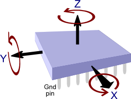
Have a look at the picture above. The 6-axis sensor, the MPU6050 fx, contains a 3-axis accelerometer that measures the acceleration i 3 different directions, X, Y and Z. In our case the acceleration is the gravity from the earth.
The other 3-axis is the gyroscope that measures the rotation around the axis. So when we start tilting the robot, the gyro values will increase and display the speed that we are rotating the robot with.
So to actually answer both of your questions, as they deal with the same confusion, look at the picture and think what happens to the values of the different axis when you tilt it around the x-axis.
By tilting the device around the x-axis, the gyroscope x-value will change and indicate the rotational speed.
The accelerometer x-axis however will stay stable, as that is still pointing out to you, as you are only tilting it around this axis.
Instead both the z-axis and y-axis values of the accelerometer will change according to the impact of the gravity on both of them.
I hope this clearified both of your questions, and you now understand why we had to chose and use the values from the axis as we did.
Kind regards
Thomas Jespersen
Hi thank you.
http://s10.postimg.org/7ekox96h5/Snap2.jpg
From MPU6050 picture in link above, if AccX (+X axis) change +10 degrees from horizontal which gyro changed?
I think Gyro-Y should be changed? so why we not use gyroYrate in line 99?.
Here is your code line 99 :
compAngleX = (0.93*(compAngleX+(gyroXrate*(double)(micros()-timer)/1000000)))+(0.07*accXangle);
Thank you again.
You code should be used with this board?
https://www.sparkfun.com/products/retired/10010
not for MPU-6050
sorry if I misunderstood.
This is a very good article and first of all ? want to thank you so much.
?m new in this topic so if my question is nonsensical please forgive me .
what is the physical meaning of P00 or p01 … ? in other words if , for example , p00 is 5 or 10 , what is the meaning of this numbers ?
thanks you.
@Beran
Please read Thomas’ explanation again. Remember that the accelerometer measures the acceleration in a certain direction (think of it as vectors), while the gyro measures the rotational speed (measured in deg/s) around an axis.
I originally posted the code for the LPR530AL, LY530ALH and ADXL335 combo, but then afterward I create a similar code for the MPU-6050. See: https://github.com/TKJElectronics/Example-Sketch-for-IMU-including-Kalman-filter/tree/master/IMU6DOF/MPU6050.
@?ükrü
Those values are part of the error covariance matrix. See the text after the headline “Predict”. It explains what it is.
hi, Lauszus, I am sorry to tell you that all pictures in your artical can’t be seen at this moment. is that caused by github parsers or some reason else?
@bow
I can see the pictures just fine. Are you still affected by the problem?
Btw they are not hosted on Github, but are written in Latex and then automatically generated by a WordPress plugin called “WP LaTeX” 😉
Hello everyone, and thanks to Lauszus for this great tutorial! I got a question:
I´m using the Microchip Motion Sense board, it has the MPU6050 and AK8975 magnetometer. Microchip also gives libraries to use this board and obtain quaternion data (in 3D). I think is possible with some operations convert this quaternion data into yaw, pitch and roll angles, to use them in a drone.
But for this dynamic systems is necessary for example a complementary or Kalman filter to obtain a good solution, and Lauszus post in a good explain of this. But i´m a bit confuse… MPU6050 can work in combination with the magnetometer and Microchip did it for this board, i ask them to get the angles and answer me to filter accel (complementary filter)… So at the end i think i need to read the gyro, accel and magnetometer and fusion in a kalman filter, maybe extended kalman???
I´ve readed many info and i think i´m a bit mixed! Also Lauszus post a link in another forum for the kalman implementation in C # but link is dead, would be great have this info for C#.
Thanks a lot!
@Andrew
You will have to use the magnetometer and gyro to estimate the yaw. Then you simply create another instance of the library and use the magnetometer angle as the first argument instead of the accelerometer.
But if you need full 3D measurement, then it would be better to use a extended Kalman filter or a DCM algorithm.
What link are you talking about?
I can´t remember now, you answered to another person something about the extended Kalman. Do you have some info about this extended version to start? Sorry but i don´t understand what you mean about the accelerometer…
Yaw -> Magnetometer and gyro.
Pitch and roll?
Thanks again Lauszus.
@Andrew
No I don’t, sorry.
Use the magnetometer and gyro for yaw and then gyro and accelerometer for pitch and roll.
https://github.com/TKJElectronics/Example-Sketch-for-IMU-including-Kalman-filter/blob/master
/IMU6DOF/MPU6050/MPU6050.ino#L89
Is the accXangle in the link above is the angle of projection of the X on YZ plane to Z-axis?
Any images are appreciated.
Thank you.
@Smad
No the accXangle is the rotation around the x-axis. See the following reply: http://blog.tkjelectronics.dk/2012/09/a-practical-approach-to-kalman-filter-and-how-to-implement-it/#comment-431999.
Hi,
first of all, I want to thank you so much for your article. it’s really helpful.
So, that’s my question: In this example:
https://github.com/TKJElectronics/KalmanFilter/blob/master/examples/MPU6050/MPU6050.ino
You calculate accXangle and accYangle that are respectively rotation about x-axis and Y-axis. But what about accZangle? can we get it (for example) from the accelerometer output only as accZangle = (atan2(accX,accY)+PI)*RAD_TO_DEG?
thank you
@Yvan
No it is not possible to estimate yaw using an accelerometer. Remember that each axis all measure the gravitational force in their respective axis – see them as vectors.
When you rotate the IMU along the z-axis none of the axis will change, as the gravitational force doesn’t change in any of the axis.
You will need a gyro and a magnetometer to estimate yaw.
Thanks a lot for this guide Lauszus! It is incredibly well explained and the Arduino library is terrific as well! I managed to get it working with Pololu minIMU v2 even though I have almost no idea about different gyro and compass (they refer to the accelerometer and magnetometer as a compass) set-up modes – in terms of refresh rates, sensitivity and so on. I will try implementing yaw as well using the magnetometer and gyro as you’ve explained in the comments before, but because I need it for a 3D application I’ll have to try using extended Kalman. I also wanted to mention that there is sample Arduino code for Pololu minIMU that uses DCM and there is a vPython program that shows 3D real time animation of the sensor – maybe you or someone reading this might be interested.
Bottom line – AMAZING GUIDE – you belong in MIT!!!
@Peter
Glad you found my guide useful 🙂
I might look into the extended Kalman filter in the future and DCM, but I’m too busy right now to dig into it!
Haha yeah maybe. I’m actually thinking of studying abroad next year, so I’m thinking of apply for MIT and see if I can get in.
Hi! thank you for your answer i understand better now.
however i have another little problem. I tried to implement that code https://github.com/TKJElectronics/KalmanFilter/blob/master/examples/MPU6050/MPU6050.ino
it works but i get i an overshoot that i can’t disregard. for example, if i try to get 180°, i would get about 190°, then go slowly to 180°. i don’t know how i can fix it
Thanks, best regards
@Yvan
It sounds like you are trusting the measurement of the accelerometer too much.
See the following part of the guide:
Hi, Thanks for the code on GitHub, I use it for my quadcopter controller (with a MPU 6050). I have got one question though. On this file: https://github.com/TKJElectronics/Example-Sketch-for-IMU-including-Kalman-filter/blob/master/IMU6DOF/MPU6050/MPU6050.ino
You set Gyro Full Scale Range to ±250deg/s. And after you write:
double gyroXrate = (double)gyroX/131.0;
I don’t see where that “131.0” comes from?
I mean it works but I’d like to understand why 🙂
Thanks, Romain
@Romain
See the Register Map datasheet: http://invensense.com/mems/gyro/documents/RM-MPU-6000A-00v4.2.pdf page 14 you can see that by writing a 0 to the FS_SEL register the range is set to ±250deg/s.
After that go see the Product Specification: http://invensense.com/mems/gyro/documents/PS-MPU-6000A-00v3.4.pdf at page 12 – there you will see if the FS_SEL register is set to 0, then sensivity is: 131 LSB/(º/s) 😉
Just a thanks for taking the time to explain this. I hope I can use some of the knowledge when I try to build a robot.
@Graham Stott
You are welcome 🙂
Thank Lauszus so much, it’s helpful for me. You’re very nice.
Firstly thanks for this great sharing!;)
I work on implementing a platform which will obtain data from quadrotor for system identification. I think about using 6 dof imu(accelerometer+gyroscope) with kalman filter to estimate quadrotor’s state. Do you think that only accelerometer and gyroscope are enough for estimating quadrotor state?
Thank you Lauszus for this wonderful tutorial. I ve been reading a bunch of papers but couldnt understand them as they assumed that I know most of the maths. Your step by step guide and the links provided were exactly what I needed.
Just a quick question, I intend to create a program which uses an accelerometer, gyro and magnetometer to get the orientation, plus maybe another reading of the roll and pitch. From the comments above I was led to believe that for such a situation I need to use an extended Kalman filter. Is that right? If so, can you please point me to some good tutorials for it.
@juve
Yes accelerometer and gyro should be enough. For instance the very popular KK2.x board use just that: http://www.hobbyking.com/hobbyking/store/uh_viewitem.asp?idproduct=49254.
@Jeremy Borg
Yes it you need to estimate 3D orientation I recommend trying some sort of DCM or extended Kalman filter, as this is best for only one axis – like I use for the Balanduino: http://www.kickstarter.com/projects/tkjelectronics/balanduino-balancing-robot-kit.
I do not know any good tutorials out there, but there are many open source flight controller for multirotors, you could just use the algorithm from one of them.
Some thoughts:
1. Even with a PERFECT gyro signal, PID control is not sufficient.
http://ctms.engin.umich.edu/CTMS/index.phpexample=InvertedPendulum§ion=ControlRootLocus
2. A controller with positive feedback is necessary.
http://web.mit.edu/klund/www/papers/UNP_pendulum.pdf
3, Your accelerometer is actually part of a positive feedback loop within the control. Other solutions which do the same are using wheel encoders for positive feedback or doing it all within the controller itself which requires neither an accelerometer nor wheel encoders.
You really do not need Kalman filtering.
@CharlieSixPack
Sorry, but the first link is dead?
I’m sorry, but I you referring to the Balanduino? Or something else?
I use the Kalman filter in combination with the encoders to balance my robot.
You can find the relevant code here: https://github.com/TKJElectronics/Balanduino/blob/master/Firmware/Balanduino/Motor.ino.
Thank you very much for a very well detailed article on Kalman Filters. You not only understand the topic very well but are able to explain it very clearly!
Hi, thanks for your magical written codes. Im using mikroC for DsPic and Pololu MinImu 9v2 as a sensor. mikroC has not micros() function. What i can write? Can i use this code instead micros() and timer? gyroYangle increasing constantly in this way.
int lastTime=0, firstTime=0;
void(){
while(1){
lastTime++;
//Codes…
gyroYrate = -(gyroY/8.75);
gyroYangle += gyroYrate*(lastTime-firstTime);
// More other codes.. }}
I think 8.75 correct coefficient for 250dps. Gyro Datasheet: http://www.pololu.com/file/0J563/L3GD20.pdf
Hi,
this is really a good piece of work that you have done. I ma also using MPU-6050 in my project that is a bit different than yours, and hope you can help me out.
I am trying to find longitudinal velocity of the vehicle using the accelerometer data. i was able to access DMP data to get the real world acceleration (gravity and orientation compensated) and the next step is to extract velocity form acceleration. I tried doing simple integration on the data but it drifts over time. I’ve done this in my code:-
If (accX > Threshold and absolute value)
{
velocity = velocity + dT*accX;
}
else
velocity = 0;
And then i saw your post on the kalman filter that sounds perfect to apply on this type of application. So, here’s the problem i am not sure about all the matrices that i/ve designed for the same. could you please have a look on them and let me know if i am on the right path.
F = [1 dT; 0 1]
H = [1 0]
X = [0 ; 0]
U = [0 ; 0]
P = [10 0 ; 0 1]
R = [1]
I guess something is wrong with my equation that?s why I am not getting the results that I want. Help will be really appreciated.
Thank you.
@Peo Neak
No you should need the sample time in seconds between each reading or you won’t be able to calculate the angle.
@Alex
That is really really hard to do – just Google it. You are not the first!
I recommend using some other kind of sensor like encoders. You will never be able to get proper measurements from the accelerometer – or it will atleast be very very hard to get precise measurements.
@Lauszus
Thanks for your reply. yea, i’ve already looked into it on google and reviewed some papers. it is hard i know. but, i really need to perform it without encoders and for that i have bought a GPS module to correct the accelerometer data every second. would you please help me in designing the state equations for the integration purpose (GPS + INS).
Thank you.
@Alex
I will not be able to do that, sorry.
@Alex
Here is a report I did implementing a Kalman Filter using the accelerometer as control input and GPS velocity and position as independent measurements.
@Dave
Thanks for sharing Dave!
Hi, thanks for the post.
I’m using the TI SensorTag to get accelerometer and gyroscope data to develop an app that can rotate a square in 3d space using that data but I’m having trouble computing the quaternion values. I need the quaternion values in order to display rotation and movment of the SensorTag device in my app. Do you know how to compute the quaternion values from the accelerometer and gyroscope data? Thanks -chris
@chris
You should check out the following site: http://www.x-io.co.uk/open-source-imu-and-ahrs-algorithms/. I have not used it myself, so unfortunately I can not help you with it.
This is a great article!!!
I have some questions about your project
(1) Because accelerometers contains the gravity and the acceleration caused by motions,it means that accelerometer will not only detect gravitational acceleration!
how did you remove the acceleration caused by motions from body frame.
(2) What rotations sequence are you choice?
(The 3 ? 2 ? 1 Euler angles are one of the most widely used parameterisations of
rotations)
(3)If you choice 3-2-1 euler angles rotations sequence,I think that your “accXangle” & “accYangle”
have problem.
It should be ? roll: accXangle=(atan2(accY, accZ) + PI) * RAD_TO_DEG;
pitch:accYangle = (atan2(-accX, squr((accZ*accZ)+(accY*accY)) + PI) * RAD_TO_DEG;
here is the equation derive:
http://avalon.tilab.com/pipermail/spine-dev/attachments/20090507/cb8e678e/getPDF-0001.pdf
http://ppt.cc/nHYQ
thanks!!
hello lauszus
Very nice article.
This may be a stupid question – I am not a programmer – but I need to know so I will ask anyway.
You write in the Github:
“This is a Kalman filter library for any microcontroller that supports float math”
Can you please tell me if I can use an Atmega 8-bit microcontroller with this filter
(Atmega16, Atmega32 or Atmega2560)?
Also, does Arduino support floating point math?
Thanks!
joseph
Plz Plz Plz HELP ME
Thanks to you finally i found a code on kalman filter.
I am currently working on my project quadrotor. I am using ADXL335 accelerometer and L3G4200D gyroscope interfaced with an atemga 128. When I check reading from accelerometer without running motors, values are accurate and stable. But when I start motors, values start to fluctuate. The more I increase the speed the more they fluctuate. I tried you code for Kalman the results seem same just less fluctuating. My gyroscope readings also give too much drift. Is this suppose to happen or am I doing something wrong.
@eric
1. That is the point of the Kalman filter. It filter out the noise.
2 and 3. You are absolutely correct. I have actually modified the example some time ago, but still need to clean it up a bit before I push it! 🙂
You should also take a look at this app-note: http://www.freescale.com/files/sensors/doc/app_note/AN3461.pdf.
@joseph
Yes they all supports the float math 🙂
@Zaki
It is caused by vibrations! Try to put some foam between the IMU and the frame – that is what I use myself.
Hello This is a very good info. I have built a segway using code that was posted online. The problem is it was using analog imu . Now it is not found. So can you please figure out a way to adjust the code to work with digital imu? it would be great help. I am willing to pay for it. The code i Have used is this
http://prototyperobotics.com/projects/the-seg-bot
@Miral
You should take a look at the newest code for the Balanduino here: https://github.com/TKJElectronics/Balanduino. It uses a digital MPU-6050 which is a combined 3-axis accelerometer and 3-axis gyroscope.
Hi Lauszus,
I feel the same that Zaki. When the engines are stopped, everything works fine, but when the motors start, the vibrations cease all useless, with disparate readings. What parameter can change or adjust and in what range in the kalman filter to try to improve the result?
Thanks for your time and for this wonderful code . 😉
I think I’m close to getting it to work.
Excuse my poor english.
@Ivan
You should make sure that you have no vibrations as I wrote to Zaki. Also you properly want to set the range to +-2000 deg/s for the gyro and +-8g for the accelerometer.
Also you can experiment with the LPF (Low pass filter) setting on the MPU-6050 – look in the datasheet for register 0x1A.
@Lauszus
Thanks for answering so fast.
I will try to isolate the vibration plate.
Where I set the range for the gyro and acc?
My accelerometers are ADXL335. And the gyros are InvenSense analog ones…
Tks for your time.
@Ivan
Unfortunatly you can not adjust the range on analog sensors.
@Lauszus
tks again Lauszus,
Would help change Q_angle, Q_gyro and R_angle variables? In that range can be moved?
@Ivan
Yes it might help to change the values. No the range will not be moved – the range has nothing to do with the Kalman filter.
@Lauszus
I mean between values ??I can change those variables … Between 0 and 1?
Q_angle = 0.001; // Between 0.001 and 0.01?
Q_bias = 0.003; //Between 0.001 and 0.01?
R_measure = 0.03; // Between 0.01 and 0.1?
@Ivan
No it is not simple as that. Please read the post for an explanation on how to tune them.
ok. Tks for all.
I have read the post, but do not understand wery well .If i get it to work, I will tell you the results.
@Lauszus hello firstly congratulations for you robot, i’m working in a proyect like yours, but i have a problem, how i can make the control of the moving without interfering with the balancing control? How do you manage to do that? i have a LQR control and the simulate is good but the real life is more difficult XD
@Alejandro
Here is how I do in the Balanduino code: https://github.com/TKJElectronics/Balanduino/blob/master/Firmware/Balanduino/Motor.ino.
Let me know if you want be to explain some of it 😉
Hi again Lauszus, after doing some tests, I found that the vibrations are not the problem. If I turn on the motor of my airplane, and its satatic on the ground, yAngle and xAngle mark the pitch and roll angles correctly. The problem starts when the airplane moves, and come into play centripetal and centrifugal forces. Then the readings go crazy and make Yangle and xAngle false angles. I understood that the combination of accelerometers and gyroscopes and corrected kalman filter these forces … the code is not ready for this? Thank you very much for your time, and, one more time, excuse my poor english.
i use the LPR530AL_LY530ALH_ADXL335 code…
@Ivan
You should take a look at the code for the MPU-6050: https://github.com/TKJElectronics/Example-Sketch-for-IMU-including-Kalman-filter/tree/master/IMU6DOF/MPU6050. I haven’t had time to update the others yet, but it is pretty low priority on my ever growing list 😉
It is most likely happening because your accelerometer values gets screwed up since I tuned the Kalman filter for my balancing robot and not for something like an airplane which is exposed to much larger g-forces than a balancing robot.
You should also try to implement a low pass filter on the values. I do this for the Balanduino using the build in filter in the MPU-6050: https://github.com/TKJElectronics/Balanduino/blob/ffbabd8e597393d51f321b94e4fe55a5c2c67d32/Firmware/Balanduino/Balanduino.ino#L220-L223.
Your english is fine 😉
thanks for the reply. I see the code you indicate me is totally different than what I used. I understand better with analog sensors. 🙁
What are the changes you say you did to adjust the kalman filter to your robot? You can freshened a little?
While I’ll read the links you indicate me and also the arduino forum post, i came to page 12 … 🙂
Thanks for your help.
@Ivan ” one more time. This explains how to adjust the values 😉
Please read the section “The measurement
I read there that is need to adjust the values ??of variance. it Refers to Q_angle, Q_bias and R_measure variables? But, these variables do not affect what you told me to tune the data to adjust the filter for the small g forces that supports your robot or the bigs one that is supporting my airplane… or affects? tks for your time.
and thanks for your patience …
@Ivan
Yes they do. For instance try to increase R_measure and it should trust new measurements less.
Thanks for the reply. I can implement a potentiometer to vary the value of R_measure in real-time … you give me an approximation of values ??should be between R_measure?
@Ivan
No I can not sorry. You will have to experiment and see.
ok. tks.
@Lauszus
Thanks for the great tutorial. I am trying to implement kalman to determine the yaw rotation of a body. will i have to use 2 separate filters? 1 for the pitch and roll with accelerometer and gyro and 1 with a magnetometer and gyro for yaw?
also say I have another method for measuring the pitch and roll, is it possible to incorporate this measurement into the equations in order to get better estimates?
@Jeremy
You will have to an instance for each axis. For instance if you want both pitch, roll and yaw then you would need three instances.
The three instances are totally independent, so if you only need it for yaw, simply just create one.
You will need to estimate pitch and roll in order to calculate yaw using the magnetometer. Please read: http://www.freescale.com/files/sensors/doc/app_note/AN4248.pdf. The equation you should use is Eqn. 22 at page 7.
@Lauszus Thank you. Do you have any pointers for my second question please? basically I have another sensor which can detect the pitch and roll, how can I incorporate it with the filter?
Thank you in advance
hello,
please help me,
im doing a project about line follower based on image processing that use kalman filter as the algorithm..
im use arduino board and cmucam4.
have any of u know how to coding this kind of algorithm..?
tq
@pearyunk
No unfortunately I don’t have any experience with that.
Thanks for the writeup…awesome! Two quick conceptual questions for learning purposes, tying into what you’ve shown above.
1) It seems you chose the output state z to be an angle (and not a rate) so that you could set z = AccelData in the innovation step, only because you had an accelerometer to fuse.
If this were a gyro-only filter, would you still put your gyro input to the u vector per above — or would you change z to be a rate output instead, and input your gyro data into z?
Actually why not have both accel angle and gyro rate in z and fuse both gyro and accel data in there at the same time, instead of gyro in u?
2) Along those lines, how did you personally decide what sensor data goes into u, and what into z? Why not flip and have accel be in u, and gyro be in z instead? Let’s say this is an IMU application. I thought u was the active control input, not the sensor reading, or does it not matter in this case?
Again, excellent and clear writeup, thanks!
hi Lauszus,
its correct this code to change the gyro and acc range to 2000 deg/s and +-8g ?
i2cData[0] = 7; // Set the sample rate to 1000Hz – 8kHz/(7+1) = 1000Hz
i2cData[1] = 0x00; // Disable FSYNC and set 260 Hz Acc filtering, 256 Hz Gyro filtering, 8 KHz sampling
i2cData[2] = 0x03; // Set Gyro Full Scale Range to ±2000deg/s
i2cData[3] = 0x02; // Set Accelerometer Full Scale Range to ±8g
Hello Lauszus,
I’ve started to study your work, but I could not understand why the F matrix has this form. Clicking on “comment” leads to nowhere. I’ve tried to reason a bit by myself, and it seems to me that there should be three state variables: angle, real angular speed and gyro bias. The angle evolves according to its previous value and the real angular speed, while the angular speed and gyro bias change according the noise only. What do you think of this?
Thank you.
Patrick
@Paul
To be honest I had seen some other code where they did it like that, so that’s why I did it as well.
@Ivan
No it should be:
i2cData[3] = 0x02 << 3; // Set Accelerometer Full Scale Range to ±8g
@patrick
I just updated the link. Please take a second look: http://blog.tkjelectronics.dk/2012/09/a-practical-approach-to-kalman-filter-and-how-to-implement-it/comment-page-1/#comment-57783 🙂
Thanks for the article.
I was wondering to implement it on arduino, but doing all these matrix calculations gets messy with arduino. They were so easy with matlab. Any idea on how one can implement this in arduino in a non-messy way?
THanks
@H J Jayakrishnan
If you read the whole blog post you would see that I end up implementing it in C. The Arduino compatible library can be found here: https://github.com/TKJElectronics/KalmanFilter.
Very nice tutorial, thank you!
Looking at the code on your Github for the ITG3205/ADXL345 IMU, I have two questions.
1. What do I change if I want an axis’ range to be -180 through 180 instead of 0 through 360?
2. How do I calculate the zero-values for my IMU? Using the default values, angle values outputted are not accurate. I have changed the starting angles to 0, as my program will start with the board flat. Changing all values to 0 seem to help slightly, but the output is still not perfect. I have tried changing the program to output the raw sensor values, and calculating the zero-values from that. This changes the end readings, but they’re not any better.
hi Lauszus
first of all thank you very much about your explanation about thw Kalman filter, finally i undesrstand almost parts of the algorithm except the covariances but that is out of my concern right now.
now i am learning your code for ITG3205_ADXL345 IMU, and i have several questons.
1. what the meaning of this code
double gyroYrate = (((double)readGyroY() – zeroValue[4]) / 14.375);
gyroYangle += gyroYrate * ((double)(micros() – timer) / 1000000);
is this the integral function? and why for the gyroXrate you add the sign (-) in the code
2.int readGyroX() { // This really measures the y-axis of the gyro
why readGyroX meassures the y-axis why not x-axis?
thanks
ok Lauszus it seem you and thomas had answered the simmilar questions like mine, sorry i’ve just read all the comments.
you know my project is to get the (yaw) orientation and position of tracked vehicle robot using 9 DOF IMU and rotary encoder with Kalman filter, so it try to combine the acclero and rotary encoder to get position, and combining the gyro and magneto to get yaw. so what do you think, do i need to use Kalman separately? cos i thought it will be easier to create the matrixs and the states if it is used separately. do you have any example how to combine gyro with magnetometer to get yaw in kalman filter? or maybe some sources? or i can edit the code for ITG3205_ADXL345 IMU may be by changing the measurement from accelero data with magneto data,can’t i?
Thanks again i really really appreciate your help
l
Hi Lauszus,
I’m working on a full-scale “Segway” for a project and I’m testing the Kalman as an alternative to a complementary filter. I’ve implemented your code, but I’m finding that the output is a order of magnitude too small (accel is reading 18 degrees and filter is outputting 1.8). This is likely due to a simple misunderstanding of concept on my part, but any suggestions you have would be greatly appreciated!
Sincerely,
Jesse
@James
1. Simply don’t add PI at these lines: https://github.com/TKJElectronics/Example-Sketch-for-IMU-including-Kalman-filter/blob/master/IMU/ITG3205_ADXL345/ITG3205_ADXL345.ino#L117 and https://github.com/TKJElectronics/Example-Sketch-for-IMU-including-Kalman-filter/blob/master/IMU/ITG3205_ADXL345/ITG3205_ADXL345.ino#L123.
2. Simply put it on one of it’s side. One of the axis should then read 1g while the others should read 0g. If they don’t this will be your zero value. Repeat this until you have this behavior on all three axis.
@faadhil
1. Please read: http://arduino.cc/forum/index.php/topic,58048.0.html where I have described what is going on.
2. Because the gyro and accelerometer are not correctly orientated on the PCB, so you will have to compensate for this in the code.
@faadhil
Please see the following example: https://github.com/TKJElectronics/Example-Sketch-for-IMU-including-Kalman-filter/tree/master/IMU/MPU6050_HMC5883L.
@Jesse
I am actually build one as well. I will write a blog post about once it is finished.
The code is available here: https://github.com/Lauszus/BalancingRobotFullSize and it is already balancing as we speak 😉
Hi, I think there’s a small bug in your implementation of step 7. On lines 75 and 76 you refer to the priori error covariance matrix (computer in lines 73 and 74) – but elements P[0][0] and P[0][1] have already been updated to posteriori state. Could you double check? I could be reading this wrong.
Otherwise, this is super helpful. Great read, thanks.
hi, i have simulated the whole thing with matlab. if i “turn” my virtual object (changing the gyro and acc values) the estimated angle is correct, but the estimated drift is totally wrong. did you watch the drift estimation in your model? i think there is a failure in the model?
rate = newRate – bias;
angle += dt * rate;
I can not understand how we can write this from the matrix. Could you please explain more?
Thanks in advance.
@dsl
You are absolutely correct. I will update it soon – I moving to San Francisco to study the next semester, so haven’t got much time right now.
@klaus
I just tried to output the unbiased rate using getRate() and it looks alright to me. Could you try to do it in hardware and check as well?
@Manh Hoang
They two lines were swapped. Please have a look now.
Please have a look at my simulation http://www.mikrocontroller.net/topic/338563
Maybe you detect an error in my simulation?
Hi Lauszus! In the definition of “Qk” where you say “accelerometer noise”, i think you should say “gyroscope noise”. Please, take a view on it. Congratulations, nice article!
Thank you for your explanation. I implement your kalman filter in my stm32f3discovery board, it’s work but I don’t know it’s good way or not.
http://www.electoday.com/index.php/topic,11432.0.html
Thanks!
Hi Lauszus, thanks for this great practical tutorial! I implemented your code succesfully. For anyone, who is interested in how Kalman filter equations are derived in a more or less intuitive manner, then this paper is a great source to begin with: http://www.cl.cam.ac.uk/~rmf25/papers/Understanding%20the%20Basis%20of%20the%20Kalman%20Filter.pdf
Again, thanks Lauszus!
Hi, Lauszus
I used your kalman filter code also for my MPU-6050
I printed out the angles from the serial port, and I compare the plot of raw angle from Acc and angle from complementary filter and kalman filter. And I find out kalman filter has a relative big delay in time than complementary filter , do you know what parameters influence the delay of kalman filter?
plot is as follows:
https://docs.google.com/document/d/1_UjrBrdR2eVgniOkUlND6guSIYaW88QAqSPfV8z3JKg/edit?usp=sharing
Since the angle theta calculated by accelerometer has no bias, why should we subtract gyro bias in the system equation? What ‘s more, these are two independent sensor.
thank you for ur perfect article dear Lauszus 🙂
Can I implement it for java and android sets?
I mean that sensors are same as robots?
did u see this code for java?
thank you again 🙂
First of all, I would like to express deep thanks to you. I tested MPU6050_HMC5883L.ino with GY-68. Pitch and roll looks like working correctly but yaw looks like not working.
And also there are something I could not understand in updateMPU6050 routine:
while (i2cRead(MPU6050, 0x3B, i2cData, 14)); // Get accelerometer and gyroscope values
accX = ((i2cData[0] << 8) | i2cData[1]);
accY = -((i2cData[2] << 8) | i2cData[3]);
accZ = ((i2cData[4] << 8) | i2cData[5]);
tempRaw = (i2cData[6] << 8) | i2cData[7];
gyroX = -(i2cData[8] << 8) | i2cData[9];
gyroY = (i2cData[10] << 8) | i2cData[11];
gyroZ = -(i2cData[12] << 8) | i2cData[13];
}
gryroX and gyroZ have – sign in just upper part. Is it correct?
And also I changed double to int for accX, accY, accZ, gyroX, gyroY, gyroZ, then it does not work.
Hi Lauszus! Thank you so much for the explanations! It helps me a lot but still I have to do more paper research regarding this topic. Have a nice day 🙂
Hello,
Thanks a lot for the contribution.
Is there any way to get Extended Kalman Filter ?
Best Regards,
@Douglas Santana is the process noise covariance matrix”.
No I don’t say that. I say that it is: “
@Thamanoon
Please take a look at the following examples: https://github.com/TKJElectronics/Example-Sketch-for-IMU-including-Kalman-filter.
@Robert
You are welcome! And thank you for that link to that article!
@xeonqq
What code are you using? Are you using my code: https://github.com/TKJElectronics/Example-Sketch-for-IMU-including-Kalman-filter/tree/master/IMU/MPU6050?
@Rocky
Please see the following comment: http://blog.tkjelectronics.dk/2012/09/a-practical-approach-to-kalman-filter-and-how-to-implement-it/comment-page-1/#comment-57783.
@soodabeh
No I have not tried this code in Java. Instead I have been using the following code for the Android application for the Balanduino: https://github.com/TKJElectronics/BalanduinoAndroidApp/blob/master/src/com/tkjelectronics/balanduino/SensorFusion.java. Source: http://www.thousand-thoughts.com/2012/03/android-sensor-fusion-tutorial/.
@Mansuk, Yang
This is because of the way the sensors were orientated. Please read: http://www.freescale.com/files/sensors/doc/app_note/AN3461.pdf and http://www.freescale.com/files/sensors/doc/app_note/AN4248.pdf.
@ary kusuma ningsih
You are welcome! 🙂
@Autorobot
I have not looked into that, sorry.
hey i have tried implementing kalman filter on IMU called GY-80 using your library but i havent got
any output but i have got errors.It would be grateful if u could find time to do it for me else please provide me with sensor fusion code on L3G4200D AND ADXL 345. WAITING FOR YOUR CODE OR REPLY
@sammy
You should have a look at the following code: https://github.com/TKJElectronics/Example-Sketch-for-IMU-including-Kalman-filter/blob/master/IMU/ITG3205_ADXL345/ITG3205_ADXL345.ino. You simply need to tweak the gyro code, so it matches the L3G4200D instead.
Hi Lauszus
Very interesting to read, I would like to build such a balancing robot, but seems like the 6DOF IMU you used is no longer available from some stores, how about other like MPU-6050?
https://www.sparkfun.com/products/11028
It also has 3-axis gyroscope and a 3-axis accelerometer, it there something I am missing?
thanks a lot,
Nir.
@Nir
You can differently use the MPU-6050. This is the sensor I have been using the most. It’s also the sensor used for the Balanduino: https://github.com/tkjelectronics/Balanduino#hardware. Also check out this example code: https://github.com/TKJElectronics/Example-Sketch-for-IMU-including-Kalman-filter/tree/master/IMU/MPU6050.
Hi,
This is a great tutorial! I have it working with my IMU now. I don’t undertsand what these values represent:
const double Q_angle = 0.001;
const double Q_gyroBias = 0.003;
const double R_angle = 0.03;
I have tried different values to get the filter response I need but I would appreciate an explanation of what they are.
Also, I initialize the filter with setAngle. What value should I use?
Thanks
Rich
@Rich
Please read the post again. It already explains it.
I would recommend taking a look at the following example: https://github.com/TKJElectronics/Example-Sketch-for-IMU-including-Kalman-filter/blob/master/IMU/MPU6050/MPU6050.ino if you want to see how to use it in practice.
Hello.
I understood how kalman filters works thanks to you.
I am not good at reading English.But your?intelligible explanation makes me?read this to the end.Thanks.
Now,I have a question.
The theta dot in the equation of step1 gives me a feeling of something wrong.
Because X(k|k-1) in the left side of the formula should be based on the previous state or estimation.
The theta dot is a previous data.
I think the theta dot should not affect the X(k|k-1).
Could you explain about it?
thanks.
@Lauszus
I see the references now. Thank you
Tak for det.
Question: Tracking the bias is done because the bias drifts slowly, yes? That is, you could make this a 1-d problem by just tracking theta and not the bias, but with constant error covariances, P and K would quickly stabilize and you’d end up with essentially a complementary filter.
I gather that by tracking bias, which varies slowly in comparison to ‘noise’, a more accurate filter is obtained.
Ikke også?
dear sir,
i hve download kalman filter library and copy paste it to arduino library folder.i add the library by correct method of library adding.but this library is not shoeing in examples section of arduino id.
i think this aws notlibrary file and it was text file having kalman filter code.i downloded it from link
https://github.com/TKJElectronics/KalmanFilter.
please anwer!
@iftikhar jatoi
Please see this guide: https://learn.adafruit.com/adafruit-all-about-arduino-libraries-install-use. It explains how to install a library correctly.
Hello Lauszus,
I am trying to build an autopilot for my small boat, based on an Arduino and the Pololu MinIMU-9 V3. Your article is really helpful to me and I have now successfully (for the most part) implemented your Kalman filter in my project, using the compass (magnetometer) and one gyro as inputs. I have one problem:
When I turn through heading North, the heading changes from 359 to 000. Obviously the Kalman filter needs a little time to stabilize again after this, which would be a problem if I would use my autopilot to steer heading North (000). Simply adding or substracting 360 degrees confuses the filter. Do you have any suggestion how to cope with this problem?
Many thanks in advance for your reply!
Thomas
@Thomas
Take a look at the following lines in the example: https://github.com/TKJElectronics/KalmanFilter/blob/master/examples/MPU6050/MPU6050.ino#L117-L123. I implemented it in the Balanduino code like so: https://github.com/TKJElectronics/Balanduino/blob/master/Firmware/Balanduino/Balanduino.ino#L319-L333.
That is helpful!
Thanks Lauszus!
Thank you, Sir! Tomorrow I´m going to play with this code.
Cheers,
Michael
How to filter the acceleration components , accX, accY and accZ using kalman filter and what should be modified in your code to achieve them.
Thank you
Thanks a lot
please can you help me to implement the kalman filter with a gyroscope and an accelerometre in SIMULINK i need it to determine indoor localisation
plz help if it’s possible email me thanks
@Lauszus
@Lauszus : I am implementing this in C#. Can you confirm whether the mistake pointed out by dsl is corrected. the following …
Hi, I think there?s a small bug in your implementation of step 7. On lines 75 and 76 you refer to the priori error covariance matrix (computer in lines 73 and 74) — but elements P[0][0] and P[0][1] have already been updated to posteriori state. Could you double check? I could be reading this wrong.
Otherwise, this is super helpful. Great read, thanks.
thanks in advance
@antix
You could try to use a low pass filter in code.
@chfakht
Sorry I don’t have time for that.
@siyum22
I’m not sure if you are referring to the following bug: https://github.com/TKJElectronics/KalmanFilter/commit/5b6f40bb143240da7f134f41b79606c383635007? But I fixed it a while ago on Github. The newest version is available here: https://github.com/TKJElectronics/KalmanFilter/blob/master/Kalman.h.
Lauszus
I’m currently working on Kalman. I have to say you are the best guy whom I know that knows what this filter is and how it is implemented!
Extremely clear and fantastic explanation
Keep on bro…
What’s the link between the real x (without hat) and the estimated state x (with hat)?
If our estimation is perfect, are they the same? The first couple of equations with the real state, we don’t use in the code?
Thank you
OK , but can you tell me HOW to do it ( if i need a s-function or just by using the support package in simulink)
i’m a newbie in the field just tell me where can i find such ressources on this because i do’nt know where to look it will be very helpfull
thanks
@Dio
Thanks 🙂
@FriendlyFool
Yes it the estimation was the same, then it would be the same. What equation are you talking about? Btw you can copy the Latex output by selecting the image and then use the following syntax: http://en.support.wordpress.com/latex/ to put it in the comments.
@chfakht
I haven’t use Simulink that much and haven’t got time to look into it, sorry.
Hello ,
I have your robot balanduino and i found it really amaizing , i use it like a demostration to some child electronic’s club !! But actually i have encoutred two problems :
1-when i compile your last balanduino code , even if i add Kalman.h file it always give me this error:
”
WARNING: library USBHost claims to run on [sam] architecture(s) and may be incompatible with your current board which runs on [avr] architecture(s).
Balanduino.ino:47:153: fatal error: Kalman.h: No such file or directory
compilation terminated.
Erreur lors de la compilation.
”
2- The buzzer make a really high unconfortable sound , is it possible to make not so unconfortable
This will help me a lot ! thank’s !!!
Hello Lauszus
compliments for your great contribution, I?ve applied the kalman library in my sketch and it works perfectly giving stable gyro rotations.
The Kalman library works comparing two measures of the same angle, now the question is: can I apply the method to other measures (eg acceleration or distance) that are ?noise? affected but not have a second value as reference? Can you drive me to some example?
Thanks a lot
Roberto
@Jo
It looks like you have not selected the Balanduino in the boards menu. Please see the following guide: http://balanduino.net/get-started.
Unfortunately you can’t play a different tone, as the frequency is fixed, but you can remove the jumper if it gets too annoying. Just remember to put it back on, so you don’t run the battery low by accident.
@Roberto
Yes that is all possible, but you will need to make another implementation, as you change the state vector. Please read this post carefully and try to understand it. Then you should be able to come up with your own code.
@Lauszus
Is it correct now?
rate = newRate - bias;
The text does not match the code.
From the formula, I get:
which you would get it the order was:
angle += dt * rate;
(Thanks for a great page by the way)
@Per Aasland
This is implemented correctly in the code: https://github.com/TKJElectronics/KalmanFilter/blob/master/Kalman.h#L47-L48, but you are right that the order of the two lines needed to be reversed in the blog post. It is updated now.
Thank you.
Great tutorial! Quick question about your H matrix. If my understanding is correct, the H matrix should map the state to the sensor value space. So in this case, it should map the angle and bias to the acceleration (because we are measuring with accelerometers) space. Zk is therefore the angular acceleration and H*Xk should be the predicted angular acceleration. This way, the innovation, Yk is measured in the same space. The problem I am having is that if H = [1 0] , and Xk = [ [theta], [bias] ], then you are not mapping to the acceleration space, but simply comparing the measured acceleration with the predicted angle. This does not seem correct to me. If you could explain your reasoning for H, that would be awesome.
Thanks!
Goodday Lauszaus,
Great article thanks. I’ve implemented the algorithm but are not convinced with the estimated position I am getting from my accl/gyro IMU. The position estimate from the Kalman does converged after a while but seems to exactly follow the position obtained from the accelerometer, which is noisy. Any ideas? Thanks.
@Roger
Actually, I found the problem. I’m implementing the Kalman filter algorithm in Simulink using a Matlab function. Its, a bit different from your c++ source code but the concept is the same. I found that I have not updated the error covariance matrix P for the next iteration. After the correction and reading IMU values, the filter really works well. Your documentation was of great help, thanks again.
Hi Lauszus,
Thank you so much for putting all this together! It helped me a lot.
I have a question. Sorry if other people have asked this before. My system has a periodic jerk input( the acceleration measurement spikes due to that) from knocking into the wall, which mess up the orientation estimation. If the system doesn’t have that jerk it works fine.
From reading your document above I feel like maybe I should adjust my process noise covariance matrix accordingly. Am I on the right track? Also I am using a sampling frequency of 500Hz.
thank you very much for your time
Hi Lasuzus,
Thank you for the filter and all the explanation, my kalman filter is working very well with positive values of my angles from the gyro and the acc but when i try to use the negative values my angle just stays at 0 and after that’s done nothing works until a reset my board, i already checked the angles one by one from the gyro and acc and y get the right negative values, i dont know whats going on, i hope you can help thanks
Hi , i didn’t understand very well this phrase :”Which is the previous estimated state based on the previous state and the estimates of the states before it.” ?? can you simplify plz
thanks
please how can i specifie the process noise covariances , i’m using a MPU-6050 and kalman filter to read value from the gyroscope and accelerometer
thnaks
@klaus
hi please can you send me your matlab code to chfakht@gmail.com
This article is excellent, easily the best explanation of Kalman I’ve found and I’ve done quite a bit of reading.
I am still struggling to adapt this to my use though. I’m going wrong somewhere and I’d really appreciate some pointers. I am working on a altimeter.
I have a atmospheric pressure sensor, a BMP180. I want to implement a kalman filter to reduce the noise on readings from this part. Height error (noise) on the BMP180 measurement is 0.25m rms. There is only one input to the filter, height. Rate (velocity) may be calculated by looking at the previous height (filter output) and the current height (measurement including noise) and dividing by dt.
The input to the filter is height in meters, I’d like the output to be height in meters.
The output of the sensor (after conversion from hPa) is in meters. The sensor has internal compensation so bias can be considered to be zero.
Based on this article I have the following:
Step 0.
P matrix initialised to be 0,0,0,0 as I’m assuming that I know the start height.
Step 1.
Rate = Measured height-Previous height / dt
Height = Measured height
Step 2.
P[0][0] += dt * (dt*P[1][1] – P[0][1] – P[1][0] + Q_height);
P[0][1] -= dt * P[1][1];
P[1][0] -= dt * P[1][1];
P[1][1] += Q_gyroBias * dt;
I don’t have a gyro, I’ve only got one input parameter, so Q-gyroBias is zero.
Step 3.
y = Current measurement – Previous filter output;
Step 4.
S = P[0][0] + R_measure
I’ve set R_measure to be 0.25 to match the rms noise in meters.
Step 5.
K[0] = P[0][0] / S;
K[1] = P[1][0] / S;
Step 6.
Height = Height +K[0]*y
Bias = Bias +K[1]*y
I think Bias will always be zero, but hey, I implemented it.
Step 7.
float P00_temp = P[0][0];
float P01_temp = P[0][1];
P[0][0] -= K[0] * P00_temp;
P[0][1] -= K[0] * P01_temp;
P[1][0] -= K[1] * P00_temp;
P[1][1] -= K[1] * P01_temp;
I’ve modelled this with an Excel spreadsheet and the kalman filter doesn’t appear to be working. Any assistance greatly appreciated. It appears that by removing one of the inputs from the filter I’ve confused the heck out of myself!
Many thanks,
Mike Veal.
@Mike Veal
Sorry, but I don’t have a lot of time at the moment, as I am writing my bachelor’s thesis.
But have you considered using a accelerometer as well? All the code I have seen use the accelerometer z-axis in the combination with a barometer in order to estimate the height.
Note that I might be working on this next semester for my flight controller. I don’t know what your timeframe is, but you can following my Github repository: https://github.com/Lauszus/LaunchPadFlightController where the code will be posted.
@ Kristian
Sadly cost is a driver as are size and power. The device is to be used on a paraglider and is battery powered.
I need to have a filter running in the next month – then it’s off to Solvenia for a week of intensive altimeter testing!
Best of luck with the thesis.
If any one else is able to help I’d greatly appreciate it.
@Mike Veal
But a MPU-6050 is less than $3 on eBay, so I can’t see no reason for not using it?
Also a Kalman filter makes no sense if you are only using one sensor! That is why it is called a sensor fusion algorithm.
Perhaps that’s what I’m struggling to understand. I can find no simplification examples with just one input.
Adding an accerometer /gyro would also make things much more complicated.
What I really need is two outputs, height and rate of change of height.
A 3 axis accelerometer / gyro could give me that infomation, but the glider will always have some forward speed as well as vertical speed.
Due to pitch, roll, yaw and repeatability of mounting axis, glider forwards motion will never be exactly on the X axis and vertical motion will never be exactly in the Z axis.
I’d have to try and separate a glider forward motion vector from the sensor output so that I could work out what constitutes vertical movement.
It sounds like a simple low pass filter would be easiest.
Many thanks for your help.
@Mike Veal
That can be compensated for by rotating the coordinate system, as I do for my flight controller as well: https://github.com/Lauszus/LaunchPadFlightController/blob/master/src/IMU.c. Then you can just use the filtered (in this case ‘accFiltered’) z-axis and integrate that.
Yes if you only want to use the barometer, then a low pass filter seems like the way to go.
Hi, nice article,
have you comparated the results from the Kalman filter and a complementary filter?, y did see the link to a web where they do that but the graphics dont look good.
I have made a comparison and with the parameters that I have used the Kalman filter and the complementary filters are practically the same, however I made a test, where I moved the IMU linearly in each axis and with the Kalman filter there was a variation of about +/-10 degrees but with the complementary filter the variation was a lot less (about +/- 2 deg).
Despite that I got similar results using both filters I dont know if I can improve the Kalman filter.
@Fabian
No not really, but to be honest I am starting to use a complimentery based filter more and more, as it is just much easier to tune, as takes less time to compute. For instance I have been using this lately with my flight controller: https://github.com/Lauszus/LaunchPadFlightController/blob/master/src/IMU.c.
Hi! I have a question about the implementation step 1. In this step you said that the apriori estimate of the angle was equal to the estimate of the previous state plus the unbiased rate times the delta time. The issue I am dwelling on is the the unbiased rate itself. This rate seems to be a diference between the rate at time k and the bias at time k-1|k-1. Is is permissible to subtract two values obtained from different time levels?
Thank you in advance!
Konstantin
P.S.: The expression in the brakets in the last row, step 1, would be
unbiased rate = theta_dot,k – theta_dot_bias,k-1|k-1
if you didn’t omit the indeces.
Hi, I’ve been checking your code about kalman filter, and I’m wondering why you divide by 131.0:
double gyroZrate = gyroZ / 131.0; // Convert to deg/s
how can I get my own value?
@Erick Medina
It has to do with the so-called Sensitivity Scale Factor. Check the following document, page 12:
MPU-6000 and MPU-6050 Product Specification Revision 3.3
The factor is 131 LSB/(deg/s) which means that you must divide the raw data to 131 in order to get real angular velocity.
How do you compare the HX (which is the angle estimate) with z (which is the accel measurement)?
Is this an approximation of some kind, and if so, what is the actual equation from which it is derived?
In the case of this being an approximation, it will only work for balancing type scenarios (small deflections), right?
@Sander
Hi,
I have the exact doubt. Did you manage to find an explanation for it?
Hi,
First of all I must say that you wrote an excellent atricle. Now let me brief you my problem , I want to estimate heading for a vechile with using IMU . I am using Murata SCC1300-D02 sensor , it has
3axis accerolmeter and 1-axis gyrometer. I am not using any magnometer so my question is that is it possible to estimate the heading(orientation) of the Vechile with the above mentioned sensor and using Kalman filter which you have written?
Nicely done. Found one typo: “control-input model” should be “control-input matrix”.
@Hasan Askari
No that will be very difficult. You didn’t say what axis the gyro were measuring, but I guess it is the z-axis. Anyway I will not recommend this, as the integration will integrate noise as well.
You might want to take a look on how I did it for my flight controller: http://blog.tkjelectronics.dk/2015/08/bachelors-thesis-launchpad-flight-controller. The relevant code is in here: https://github.com/Lauszus/LaunchPadFlightController/blob/master/src/IMU.c.
You might also want to read the chapter “Estimation of the orientation” in my report: https://github.com/Lauszus/LaunchPadFlightController/blob/master/docs/Kristian%20Sloth%20Lauszus%20-%20Flight%20Controller%20for%20Quad%20Rotor%20Helicopter%20in%20X-configuration.pdf.
@Law
Not according to Wiki: https://en.wikipedia.org/wiki/Kalman_filter#Underlying_dynamic_system_model, but thanks for your feedback anyway!
Hi..excellent article..thanks a ton.
I?ve been trying to estimate altitude from barometer(measured) and accelerometer(predicts and also gravity removed somehow)..so how do I find the covariance matrix considering if I know the error in accelerometer..how do I find error in position and velocity.?
@spookymelonhead
I did this for my flight controller: http://blog.tkjelectronics.dk/2015/08/bachelors-thesis-launchpad-flight-controller. You can read more about it in the report: https://github.com/Lauszus/LaunchPadFlightController/raw/master/docs/Kristian%20Sloth%20Lauszus%20-%20Flight%20Controller%20for%20Quad%20Rotor%20Helicopter%20in%20X-configuration.pdf.
The relevant code is here: https://github.com/Lauszus/LaunchPadFlightController/blob/master/src/AltitudeHold.c.
Note that I did not use a Kalman filter, but uses a simple complimentary filter. The result can be seen here: https://www.youtube.com/watch?v=HXX-2L1hKgI
@Kristian Sloth Lauszus
Hi..may I ask..How did you came up with the idea of using (theta dot b) as second state variable?
@Kristian Sloth Lauszus
Hi, I have one question regarding the angle. In your code you have mentioned an argument as new angle. Can you tell me what is new angle representing here?
Best Regards,
Umair
@spookymelonhead
I saw some other code where they did that as well.
@Muhammad Umair Masood
newAngle is the angle measured using the accelerometer.
The derivation is missing a state variable (theta dot) and the rate gyro measurement should be used as a measurement, not as a “control variable”.
A more complete discussion of the problem is given in http://home.earthlink.net/~schultdw/bbot/bbot.html
@Jim Remington
I know that the article has some shortcomings, but I don’t have time to write a new one at the moment. But remember that I wrote this article back in High School before I was actually formally taught any of this stuff.
and here’s another good source for learning Kalman
https://www.youtube.com/playlist?list=PLX2gX-ftPVXU3oUFNATxGXY90AULiqnWT
@spookymelonhead
Thanks for the link 😀
Hi Kristian,
Nice article. I am interested to use kalman filter to my following application can u suggest which code i use.
1. My application is to measure Tilt angle in X & Y direction +/- 35 degrees. I use analog
device ADIS16209 (Inclinometer & accelerometer) with ADIS16265 (digital gyroscope). I interested to measure both X & Y direction accurate tilt angle in dynamic condition also.
2. Presently I measure accurate tilt angle in static condition without gyroscope.
Please suggest best algorithm
Hey..quick question..When we write
Yk= Zk- (H * Xk)
which is basically subtraction between measured value and predicted value.
we set H matrix equals as 1 for angle and 0 for bias. That implies no prediction for the Gyro bias via the model and No measurement for Gyro bias too.
But when it comes to updating the predicted states i.e
New_angle= Predicted_angle + Kalman_gain * (Innovation)
we are updating Gyro Bias
GyroBias_est= GyroBias_est + Kalman_gain * Innovation
so same innovation is used for getting new estimates for angle and bias.
I know its correct..since with the help of measured value, it will try to correct Gyro_bias..but it still seems odd..we updated bias with the innovation calculated for angle..!!
In the process noise covariance matrix, Qk, I can understand why Q_angle gets multiplied by dt since the state you’re estimating is the angle, but I do not understand why Q_gyroBias gets multiplied by dt when the state being estimated is the gyro bias, which if I understand correctly, is an angular velocity. Can you clarify this? Can you also clarify if Q_angle is the covariance matrix of the gyroscope measurement and not the accelerometer measurement?
Thanks
Awesome tutorial! helped me a lot.. thanks dude!
Hei, one question, I’m on a project that receive data from 3 GPS’s and I’m being use a kalman filter to estimate a better location for my quadcopter..
About R matrix and Q matrix, How can I get these values ? In the diagonal matrix Q I put the measures from either GPS ?…
Thank you!!
@Fabian
I have tried it and I’ve found out that complementary filter and kalman filter results are almost the same!
I wonder if it has anything to do with the tuning..
@Abdullah Kahraman
A Kalman filter with constant gain (not extended Kalman filter) results in the same as a complimentary filter. The difference is that the Kalman filter helps with the tuning/frequency selection from a model-based description of the system to be measured.
Wow….this is the best explanation of the Kalman Filter I have ever read! Thank you very much! The KF is something I have always wanted to understand without having to know the science. I will be working to port this over to a Intel Curie using Arduino.
FYI – for some reason I cannot get your Arduino code to compile. The following error pops up on the I2C.ino
exit status 1
‘While’ was not declared in this scope
I will share the Curie code on git once I get it completed.
@Kristian Sloth Lauszus @Thomas Jespersen
Hi, I have one question about the newAngle measured using the accelerometer.
when I put the phone on a table, and rotate it around the z-axis of gyro.
what I want is to calculate the angle of rotating.
I can get the gyroRate from the z-axis of gyro.
But I don’t know what is the newAngle in this case. I mean I don’t know the newAngle is between which two things(lines or axises)?
Thank you!
Hi,
I am an engineer from taiwan.
I see the web have a lot of good stuff.
and I want to ask is there a accelerometer sensor measured in wheel revolutions per second.
I find a lot of web site but I don’t find such like here very professional.
I use the BMA250E accelerometer sensor and mounted on bicycle wheel hub for measured in wheel revolutions per second.
But I got a lot of noisy sine wave and try to implement Kalman on project.
@Mark Ingle
This sounds strange, as it is simply just a while loop?
@jiayi xin
You can not measure the yaw (rotation around the z-axis) using an accelerometer. You will need to use a magnetometer.
You should take a look on how I do it for my flight controller: http://blog.tkjelectronics.dk/2015/08/bachelors-thesis-launchpad-flight-controller/. Please read the theory section in the report: https://github.com/Lauszus/LaunchPadFlightController/raw/master/docs/Kristian%20Sloth%20Lauszus%20-%20Flight%20Controller%20for%20Quad%20Rotor%20Helicopter%20in%20X-configuration.pdf. Here is the relevant code: https://github.com/Lauszus/LaunchPadFlightController/blob/master/src/IMU.c.
@Vincent Kuo
Why not use a simple encoder?
@Vincent Kuo
Of course you will get a lot of sine waves on the measurements – this is not noise but your actual movement when you rotate an accelerometer placed in the center of a wheel.
As Kristian says it might be better to install some kind of encoder. Maybe a hall effect encoder can be installed depending on the velocity resolution of interest.
I studied Kalman Filter for a whole year during my final year undergrad project in 2011 but reading your blog feels like I just grasped the whole concept clearly. I am now working with IMUs. I might follow your blog to calculate degrees precisely. I’ll probably cite your GitHub project in my work.
Great work! I hope you become a teacher some day. Very few people can clarify difficult concepts this easily.
@Shamir Alavi
Thank you for your kind words!
@Lauszus
if the 15 degree/s is negative ? What would happend?
I realised some error ,but maybe I m wrong .for example unity is inconsistent for Q matrix ,also Q bias has to be dps unity and Q angle vektor is degree in this case Qk matris should multiply [1 deltaT]'(transpose ) and also gyro data can take negative values in this case bias value by status reducing or increasing .
as a result for P matris : I met again unity problem maybe is not important but Im obsession for it.Am I wrong .Also I wonder if I wanna control with a command in this case I should use a +control value in equality (Uk matrix) that will give extra angle to my device .Am I right? Thanks to reply.
A should be [1 -1;0 1] , because b is angle but you are getting like dps and multiply deltaT give degree(bk = b(k-1) +K1(zk – H*Teta) ) .And As far as I see because of -1 ,b value will decrease our angle and less bias or no bias I dont know Im didn’t try yet.And with bias += K[1]*y , b is fixing its seld as – or + . Am I right .
Your link to the “PDF” mentioned in your blog seems to be broken? I tried to click on the one for “more information on complimentary filters,” but all I got was a 404 error from an MIT webpage…
Hello Kristian, just wanted to say that I’m impressed by your explanation of the filter, and also the implementation notes proved highly useful for my current project. Actually I understood more your explanation that some specialiced books I’ve been checking. Also, using the angle and its bias as states, only linearly related to the sampling period was brilliantly simple.
So I wonder, if I wanted to further my understanding and / or go beyond, for example to optimal control, what bibliography do you recommend? What did you use to understand this so well?
Thanks a lot.
great article , but i want to ask about if you have eny reffrencies of implementing kalman filter with two measred data ( two diffrent sensors ) and exact data ???
Great article! However I compared results of Matrix and C code equations and found a mistake:
In Step 2 You unnecessary multiply “Q” by “delta t” while solving the equations .
So in C code:
(1) Should be: P[0][0] += dt * (dt*P[1][1] – P[0][1] – P[1][0]) + Q_angle;
(4) Should be: P[1][1] += Q_gyroBias;
Hi Kristian!
This is awesome!
@Krzychu
I also noticed the mistake with Q_angle. The accelerometer does not accumulate noise and should therefore not be multiplied by dt. But I do think the Q_gyrobias should be multiplied with dt. If dt is not constant, the gyro drift will be different each timestep.
Did you do any measurements with your code to see if you get a better signal with your calculations?
@Krzychu
Since I cannot delete my comment I will have to respond to my own comment. On further investigation, I realized that you were right on the gyro bias as well. The time step is being taken care of by the F matrix when transitioning from the previous P covariance matrix to the current a priori P matrix.
Thanks this by far the best explanation of KF i have seen.I am working on a collision avoidance protocol for a quadcopter.i will be using 8 sensors(a pair of ultrasonic and infrared sensors on each arm.). i want to implement a KF for this.please need your ideas on this
Hi.
Thanks for your great work!
I have project to sense the angle using gyro. But as MEMS gyros has lot of errors (like, temp drift, G-force drift, bias instability and so on) and i should integrate from MEMS gyro output to reach the angle, the integration will cause to lots of errors.
The kalman is great idea for compensation.
I used ST digital IMU as sensor.
What is your suggestion for compensation of G-force with accl and gyro?
thanks
Hi, first of all great article.
I just got a bit confused when you described the acceleration as the measurement when before it was all about the angles. (part “update”). Not sure if it’s a mistake or I didn’t understood right.
greetings
@Peter
ah found the existing question myself.
But I have another one .. what does the function “micros()” in your C++ exemple do ? Couldn’t find any explanation online.
@Lauszus you are a saviour. Thank you for the comprehensive explanation on such a topic. With your help, I have designed Kalman filter on SIMULINK model.
Great work!!
@Krzychu
I think the same as you…
Hi, I tried to understand how to use Kalman filter but it’s really hard !
I’m trying to make a height measurement for BMX (Bicycle cross) because when I’m doing quaterpipe, I can’t know how high I’m going. I want to use 3 axis Accelerator and Gyro. I think that’s quite simple because there’s no PID of action, just a measurement on Z axis. My problem is that I’m loosing my mind on rotateV and other functions.
Can you show me a height (or altitude in meter) measurement routine ?
Thx,
Fred
@Fred
An accelerometer is really not suited for measuring height, neither is the gyroscope.
The accelerometer measures accelerations whereof the gyroscope measures rotation – none of these measures absolute or just even relative height.
However the accelerometer measurements could possibly be double integrated to lead to an estimate of the height, though possibly heavily drifting.
What you want to use is probably a combination of an accelerometer and a barometer or other relative altitude sensor.
@Lauszus
where is the tuning guide??
hi:) thanks for your great work
I just want to know which filter is better and have less Time complexity and which is more accurate>>> and why?
can you help me?
hello,
This is really nice for the briefing of kalman filter. But is there any way I can learn it general way.
Basically I want to know how do we find the values or dependencies of F and B
please guide
Hi,
is it possible that there might be a wrong sign in the F matrix? I’ve tried to implement this as-is for smoothing gyros based on the rates they spit out and the torques requested by the PID controller. When I specify -dT in F[0,1] as above, bias builds up exponentially, if I specify dT, bias appears to work fine.
Thanks for any insight.
@Tom Servo
-dT is indeed correct as you want to subtract the bias from the measurement.
In you write out the first row of the predict equation (related to the angle, theta) you would like it to be:
Theta_k|k-1 = Theta_k-1|k-1 + dT*(gyro_meas – bias)
And by collecting the terms related to the state vector:
Theta_k|k-1 = Theta_k-1|k-1 – dT*bias + dT*gyro_meas
You thus get the first row of the state transition matrix:
[1 -dT]
Hi, great work.
I am currently using a mpu6050 and have implemented your Kalman filter. I have one problem however. The gyroscope “newrate” is not actually doing anything. The output from the Kalman filter only follows the accelerometer, but more smooth.
Is this normal?
@Brian
It sounds like you are not updating the “newrate” variable with your latest gyroscope measurement?
Keep in mind that both gyroscope measurements and accelerometer measurements are fused by this described Kalman filter. Gyroscope measurements go into “newRate” and accelerometer angle measurements go into “newAngle”.
Hi. Your step 6 does not make sense. Since the vector y is
(newAngle – angle, 0) from step 3, step 6 is:
angle += K[0] * (newAngle – angle);
bias += K[1] * 0;
Why do you copy the first entry of the y-vector to the second one in step 6?
@theBest as shown in the equation:

This is just how the Kalman filter works. The Kalman filter estimates a Kalman gain which has to be applied to the innovation,
Remember that the innovation is only a scalar in this implementation. So Step 6 is all correct!
@Tommy
I realize this is old, but the Q matrix should actually have a dt^2 term to keep it consistent over changing timesteps. The reason is that the noise in the gyro reading is indeed multiplied by dt, BUT, the formal derivation of the KF squares the (df/dw) term, where w is the noise:
theta_k = theta_{k-1} + dt [ gyro_reading + gyro_noise + gyro_bias ]
d [theta_k] / d [gyro_noise] = dt
The other way of looking at it is dt^2 shows up in A P A’, so it’s consistent for dt^2 to show up in Q.
You have, “As you can see the Q_k covariance matrix depends on the current time k, so the accelerometer variance Q_\theta and the variance of the bias Q_{\dot{\theta}_b} is multiplied by the delta time \Delta t.”
But Q_\theta refers to the gyroscope variance, not the accelerometer.
Maybe my question is off-topic, so feel free to redirect me to those who may concern.
As said in the article, the bias is the amount the gyro has drifted. Therefore, as far as I understand, to find the gyro bias one should:
1. make the gyro rotate about a known angle (say 360°)
2. integrate the values so you get actual gyroscope output in terms of the angle
3. subtract this output from the known angle (360°).
4. divide the result by the total integration time
By using this procedure I always obtain very big and different values for the gyro bias, such as 0.78 rad/s, -0.11 rad/s, 0.5 rad/s.
My question is: am I using the correct procedure?
@Ago
The Gyro bias is estimated automatically by the filter. So there is no need to calibrate this bias away manually.
Your approach is correct but will likely fail due to inaccuracies in your “known angle”.
A better approach to estimate the bias is to hold the sensor completely steady and average the gyroscope angular velocity values over a period of time.
thanks a lot
Can using in IMU 9 DoF GY-85
Great article!!
Can you give me a program with using GY-85?
@Iqbal
The mentioned Kalman filter and software algorithm described in this article is not for 9 DOF.
Please consider the Madgwick algorithm for a quick and easy to use 9 DOF AHRS algorithm: http://x-io.co.uk/open-source-imu-and-ahrs-algorithms/
@thomas
thank you
can i use this filter when combining adxl345 + itg3000?
thank you
can i use kalman filter when combining adxl345 + itg3000?
@Thomas Jespersen
thank you
can i use this filter when combining adxl345 + itg3000?
great explanation ,
thank you,
and why you do not talk about other filter (nonlinear filter)?
if you do ,it will be kind of you to give an example with explanation like you great article .
Thanks for the great explanation
@Greg
Where can I find more information about what are you saying? I realized the incosistency whith the unities when it was multiplied by dt, but I´m not sure
1. I indeed believe that the covariance matrix presented here is correct. The noise term from the first element of Q is the result of an integration of the white noise in the gyroscope, while the noise term from the second element of Q models the bias random walk rate.
2. It is correct to multiply with just dt (as done/shown in the blog post) and not dt^2. The reason for this lies in the noise model, where the gyroscope measurements are modelled with a white noise component. From Probability Theory we know that integrating white noise over an interval of dt, leads to a Wiener process, or in the discrete case a random walk whose sample covariance is scaled by dt and not by dt^2.
See Appendix E of: https://arxiv.org/pdf/1711.02508.pdf
See also equation 443 in this thesis where you get to see both the dt^2 and dt term.
Hello,
Thank you for the article. I am trying to fuse magnetometer and gyroscope data to estimate yaw. My question is can I just feed the magnetometer angles in the newAngle variable (used to calculate innovation) in the code to do this or do I need to include the magnetometer heading in the state vector?
Regards
@B
If you already have the gravity compensated yaw angle from your magnetometer you can indeed use our filter here to fusion this angle measurement with the gyroscope measurement to estimate the yaw heading. Keep in mind that if your application tilts substantially you would need to compensate for this tilt in the z-axis gyroscope measurement.
Hey Thomas,
Thanks for great article, it is a bit problem for me to get the idea about how you resolve accelerometer transition problem, can you help me to get the idea?
Thanks
@olgaç özarslan
“Accelerometer transition problem” – What are you referring to here?
Hello, thank you for your sharing! It’s a great tutorial! But I still have some questions for this tutorial:
1. “Q_k is the process noise covariance matrix and in this case the covariance matrix of the state estimate of the accelerometer and bias.” menthion in the article is confusing me, I think the Q_k is suppose to be the covariance matrix of the GYRO and bias?
2. Can you explain why you used gyro as the control input?
3. Is that OK to use degree and angular rate of gyro to build the state matrix? Then the state of system could be [degree; rate] = [1, dt; 0, 1] * [degree; rate]. But it seems how to define the Q_k is a problem in this situation because degree and rate are not independent. I’m curious to what’s your opinion about this.
Thanks
The accelerometer signal consists of both gravity and motor thrust signals (ignoring aerodynamics).
Wouldn’t a Kalman filter applied on accelerometer and gyroscope signals in a rocket application be “tricked” by the fact that the accelerometer is not showing the actual down direction due to the fact that is is measuring gravity and rocket motor thrust?
@Lauszus
Hi, you said in the article “I know that the -\Delta t might seem confusing, but it will make sense later (take a look at my comment).” I couldn’t find the explanation of delta t, I am trying to understand your implementation and only thing I could not figure out. Thanks
@Hikmet
Please see this comment: https://blog.tkjelectronics.dk/2012/09/a-practical-approach-to-kalman-filter-and-how-to-implement-it/#comment-125398
You are correct @Alex
An accelerometer on board a drone can not be used to determine which direction is down when the drone is in flight, since gravity will not affect the accelerometer in flight, since gravity is cancelled by the propellers/thrust to make the drone fly and hover.
When the drone is flying it is therefore WRONG to assume that the accelerometer can be used to determine roll angle from the assumption of it measuring the gravity direction.
A lot of people use the accelerometer and complementary incorrectly on drones due to this misunderstanding.
What happens when the accelerometer is used in a complementary filter as shown in this video, is basically that you end up with a dead-reckoning based estimate, since your accelerometer measurements (in the local drone frame) will always point in the direction of the thrusters plus the actual acceleration of the drone. This makes the estimate very vulnerable to the gyro bias resulting in a drifting estimate.
What saves you then would be any type of position feedback, e.g. GPS or optical flow, since this makes the gyro bias observable.
But without position feedback you could rather just fly your drone with a gyroscope only!
For more information, feel free to read Chapter 2.1 and Appendix B of this rapport: http://tkjelectronics.dk/uploads/autonomous_indoor_navigation_for_drones_using_vision-based_guidance.pdf
Thank you